Supercharge Your Innovation With Domain-Expert AI Agents!

Drainage guide device for intensive care

A guiding device, a serious technology, applied in the directions of suction equipment, cleaning methods and utensils, cleaning hollow objects, etc., can solve the problems of troublesome cleaning, time-consuming and laborious, affecting the user's experience of using the drainage device, etc., to improve the use experience and facilitate the movement. Effect

Inactive Publication Date: 2020-04-21
徐敏
View PDF1 Cites 2 Cited by
  • Summary
  • Abstract
  • Description
  • Claims
  • Application Information

AI Technical Summary

Problems solved by technology

[0003] However, due to the relatively simple structure of the diverter, the lack of a corresponding cleaning mechanism on the diverter makes it troublesome for the user to clean the inner wall of the waste liquid tank on the diverter, time-consuming and laborious, and affects the user's experience of using the diverter

Method used


Image

  • Drainage guide device for intensive care
  • Drainage guide device for intensive care
  • Drainage guide device for intensive care

Examples


Embodiment 1

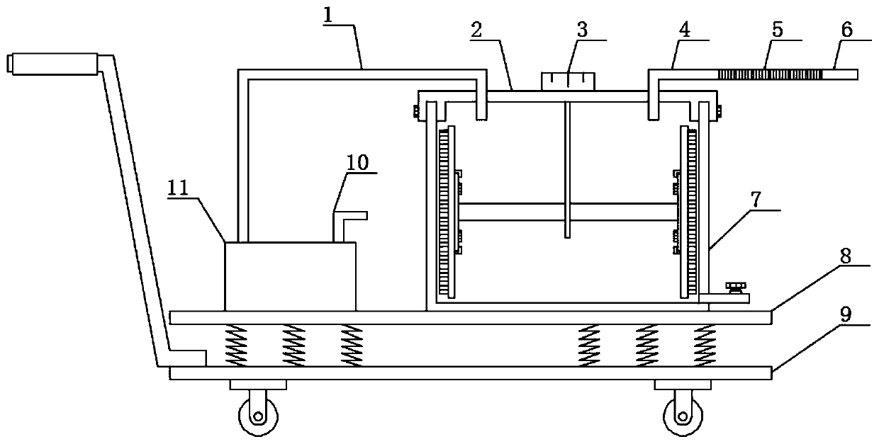
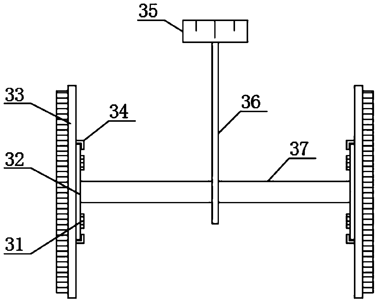
[0021] See Figure 1-Figure 3 , The present invention provides a technical solution: a drainage guide device for intensive care, including a cleaning mechanism 3, a supporting bottom plate 8 and a supporting mechanism 9. The upper surface of the supporting bottom plate 8 is provided with a waste liquid tank 7 and a waste liquid tank 7 The bottom end and the supporting bottom plate 8 are fixedly connected by welding. The top cover 2 is provided on the top of the waste liquid tank 7, and an air pump 11 is provided on one side of the waste liquid tank 7, and the connection between the air pump 11 and the top cover 2 is provided with a pump. The air pipe 1, the other end of the upper surface of the suction pump 11 is provided with an exhaust pipe 10, the other end of the upper surface of the top cover 2 is provided with a first connecting pipe 4, and one side of the first connecting pipe 4 is provided with a diversion pipe 6. A connecting hose 5 is provided at the connection betwee...

Embodiment 2

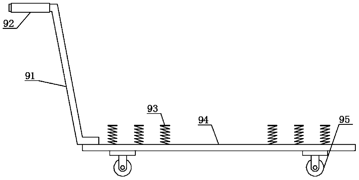
[0025] See Figure 1-Figure 3 On the basis of embodiment 1, in order to enrich the functions of the drainage guide device, in this embodiment, preferably, a supporting mechanism 9 is provided under the supporting bottom plate 8, and the supporting mechanism 9 includes a first supporting plate 94. The connection between the support plate 94 and the support bottom plate 8 is welded with a shock-absorbing spring 93. The shock-absorbing spring 93 converts the received kinetic energy into its own elastic potential energy, thereby playing a shock-absorbing effect. Both ends of the lower surface of the first support plate 94 A ground wheel 95 is provided, and the top end of the ground wheel 95 is fixedly connected to the first support plate 94 by welding;

[0026] In order to make the drainage guide device more convenient to move, in this embodiment, preferably, a handle 91 is welded on one side of the first support plate 94, and an anti-slip sleeve 92 is provided on the end of the hand...


PUM


Abstract

The invention discloses a drainage guide device for intensive care, and belongs to the technical field of medical nursing equipment. The drainage guide device comprises a cleaning mechanism, a supporting bottom plate and a supporting mechanism, wherein a waste liquid tank is arranged at one end of the upper surface of the supporting bottom plate, the bottom end of the waste liquid tank is fixedlyconnected with the supporting bottom plate in a welded mode, a top cover is arranged at the top end of the waste liquid tank, a gas sucking pump is arranged on one side of the waste liquid tank, a gassucking pipe is arranged at the joint of the gas sucking pump and the top cover, an exhaust pipe is arranged at the other end of the upper surface of the gas sucking pump, a first connecting pipe isarranged at the other end of the upper surface of the top cover, and a flow guide pipe is arranged on one side of the first connecting pipe. According to the invention, by arranging the cleaning mechanism on the drainage guide device, a user can brush the inner wall of the waste liquid tank through the cleaning brush plate on the cleaning mechanism, so that the user can clean the inner wall of thewaste liquid tank conveniently in a time-saving and labor-saving manner, and the use experience of the user on the drainage guide device is improved.

Description

Technical field [0001] The invention belongs to the technical field of medical care equipment, and specifically relates to a drainage guide device for intensive care. Background technique [0002] Chinese Patent (Publication No. CN207941070U) discloses a flushable and disinfectable drainage device for critical care, including a device body; the device body is composed of a negative pressure device and a waste liquid tank, and an elastic cavity is arranged in the middle of the negative pressure device. The upper side is provided with a pressure plate, the upper side of the pressure plate is provided with a one-way valve, the bottom end of the elastic cavity is provided with a base, and one side of the base is provided with a one-way valve two. The hole extends into the waste liquid tank, and the through hole is located on the upper side of the upper cover of the waste liquid tank. A drainage head is arranged on the outside of the device body. One end of the drainage head is connec...

Claims


Application Information

Patent Timeline
Patent Type & Authority Applications(China)
IPC IPC(8): A61M1/00B08B9/087
CPCA61M1/0023B08B9/087
Inventor 徐敏
Owner 徐敏
Features
  • R&D
  • Intellectual Property
  • Life Sciences
  • Materials
  • Tech Scout
  • Unparalleled Data Quality
  • Higher Quality Content
  • 60% Fewer Hallucinations
Learn More