Accumulated snow removing device for outdoor electrical equipment

A technology for power equipment and cleaning devices, applied in cleaning methods and appliances, cleaning methods using tools, cleaning methods using gas flow, etc., can solve problems such as reducing the service life of power equipment, hidden safety hazards of power equipment, and large energy consumption , to achieve the effect of ensuring work safety, improving snow cleaning efficiency and prolonging service life

Inactive Publication Date: 2020-04-21
STATE GRID SHANDONG ELECTRIC POWER +1
View PDF8 Cites 4 Cited by
  • Summary
  • Abstract
  • Description
  • Claims
  • Application Information

AI Technical Summary

Problems solved by technology

[0002] Most of the power equipment is installed outdoors. In heavy snow weather, it is easy to be covered and buried by snow, which affects the working efficiency of the power equipment and reduces the service life of the power equipment. Therefore, it is necessary to clear the snow in time to ensure the working efficiency of the power equipment. Extended service life
[0003] Power equipment will be covered with thick snow in heavy snow, and the snow will freeze and freeze in cold weather, which will bring a great workload to the snow removal device, consume a lot of energy, and work The efficiency is low. In addition, when clearing snow, some light snow cannot be removed completely, so that the light snow turns into water after melting, causing safety hazards to power equipment
[0004] Moreover, when the snow removal device is clearing snow, the snow pusher will work in a low temperature environment for a long time, which will easily freeze the device and affect the working effect and service life of the device. Therefore, there is an urgent need for an outdoor power equipment for snow removal. devices to solve existing problems

Method used


Image

  • Accumulated snow removing device for outdoor electrical equipment
  • Accumulated snow removing device for outdoor electrical equipment
  • Accumulated snow removing device for outdoor electrical equipment

Examples


Embodiment Construction

[0039] The present invention will be further described below in conjunction with accompanying drawing:

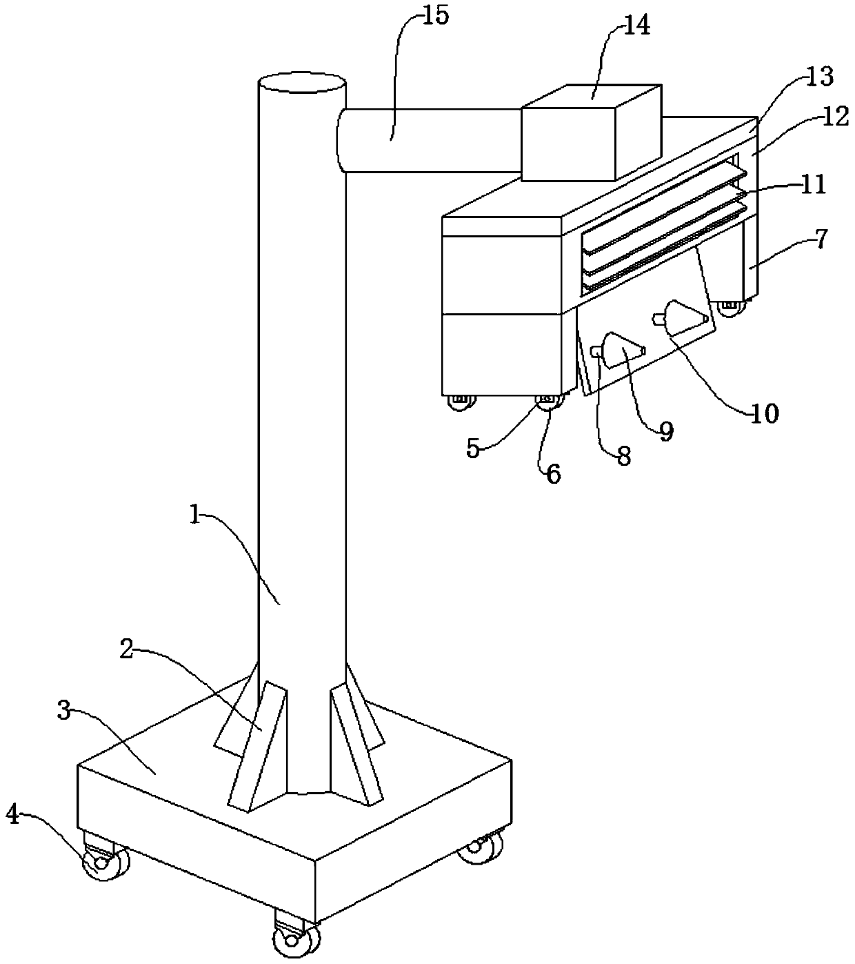
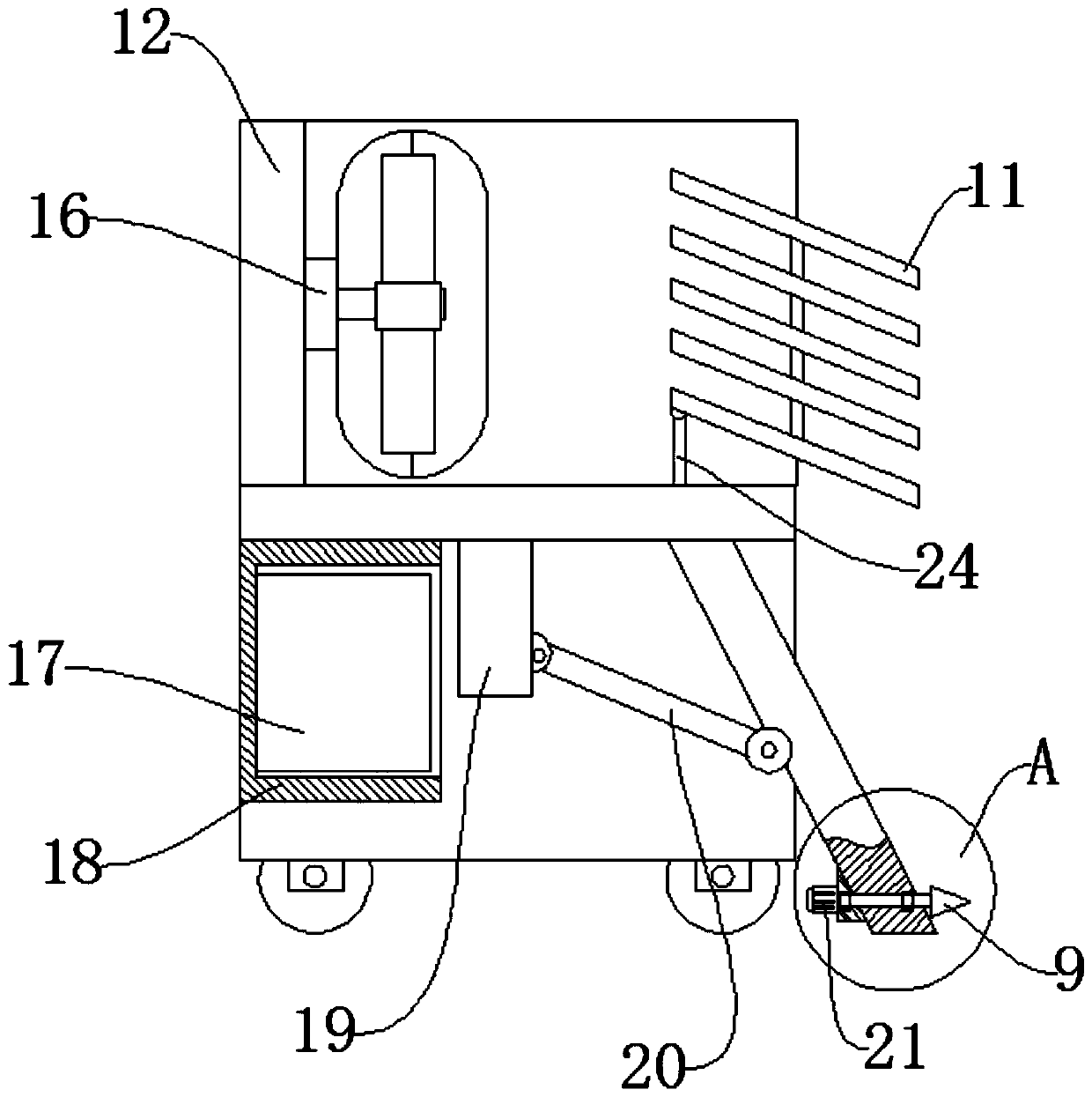
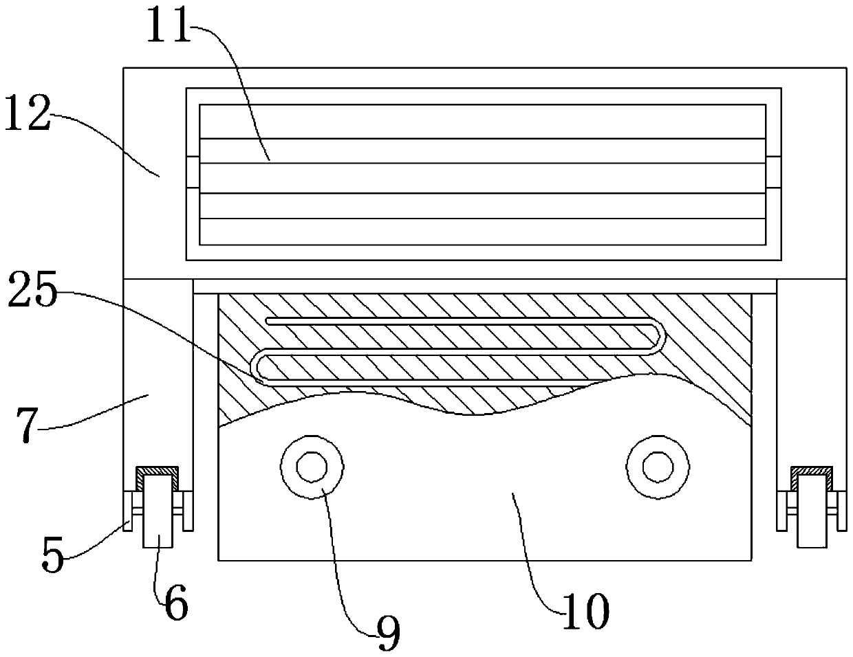
[0040] Such as Figure 1-Figure 6 As shown, a snow removal device for outdoor power equipment includes a box body 12, a snow pusher 10 and a snow drill 9, side plates 7 are welded on both sides of the bottom end of the box body 12, and the bottom of the box body 12 rotates The snow pusher 10 is connected, the side wall of the back of the snow pusher 10 is connected with a slant plate 22 by bolts, the side wall of the slant plate 22 is connected with a motor 21 by bolts, and the transmission of the motor 21 The output end is connected with a rotating shaft 8 through a key, and a bearing 23 is nested between the rotating shaft 8 and the inclined plate 22 and the snow pusher 10 , and the end of the rotating shaft 8 close to the snow pusher 10 is connected by bolts There are 9 of the clear snow drills.

[0041]In this embodiment, the upper end of the box body 12 is connected ...


PUM


Abstract

The invention discloses an accumulated snow removing device for outdoor electrical equipment. The accumulated snow removing device comprises a box, a snow pushing plate and a snow removing drill. Sideplates are welded to the two sides of the bottom end of the box. The snow pushing plate is connected to the bottom of the box in a rotating manner. An oblique plate is connected to the side wall of the back of the snow pushing plate through bolts. A motor is connected to the side wall of the oblique plate through bolts. A rotating shaft is connected to the transmission output end of the motor through keys. Bearings are arranged between the rotating shaft, the oblique plate and the snow pushing plate in an embedded manner. The snow removing drill is connected to one end, close to the snow pushing plate, of the rotating shaft through bolts. The accumulated snow removing device has the beneficial effects that by arranging the motor, the oblique plate and the snow removing drill, heavy snow and ice can be effectively smashed in a rotating manner, the snow removing efficiency is improved, the work and carry load of the device are reduced, and meanwhile, the energy consumption of the deviceis reduced.

Description

technical field [0001] The invention relates to the technical field of snow removal devices, in particular to a snow removal device for outdoor power equipment. Background technique [0002] Most of the power equipment is installed outdoors. In heavy snow weather, it is easy to be covered and buried by snow, which affects the working efficiency of the power equipment and reduces the service life of the power equipment. Therefore, it is necessary to clear the snow in time to ensure the working efficiency of the power equipment. Extended service life. [0003] Power equipment will be covered with thick snow in heavy snow, and the snow will freeze and freeze in cold weather, which will bring a great workload to the snow removal device, consume a lot of energy, and work Efficiency is low, and in addition, when clearing snow accumulation, can not clean up some light snows, make light snows become water after melting, cause potential safety hazard to electric equipment. [0004]...

Claims


Application Information

Patent Timeline
Patent Type & Authority Applications(China)
IPC IPC(8): B08B1/00B08B13/00B02C18/14B08B5/02
CPCB02C18/14B08B1/005B08B5/02B08B13/00
Inventor 崔国柱王砥凡王东阳林刚主晓琨曲小康沈宏奇
Owner STATE GRID SHANDONG ELECTRIC POWER
Why Eureka
Try Eureka