High-voltage line deicing device based on electric cylinder knocking

A technology of high-voltage wires and electric cylinders, which is applied to the installation of cables, electrical components, overhead installations, etc., and can solve problems such as disconnection, stretching, and low efficiency

Pending Publication Date: 2021-06-11
LUDONG UNIVERSITY
View PDF0 Cites 4 Cited by
  • Summary
  • Abstract
  • Description
  • Claims
  • Application Information

AI Technical Summary

Problems solved by technology

[0003] 1. The thermal deicing method is currently the most widely used anti-icing and deicing method. First, the "short-circuit deicing" scheme can realize remote deicing, but this technology is stretched when it is used for 500KV and above lines; the other is more used The thermal ice melting method is a direct current ice melting technology. The disadvantage of this method is that the ice-covered line needs to be disconnected from the power grid before melting the ice, and then the two wires are connected to form a loop and then a DC power supply is applied. The power supply can only be restored after the ice is melted.
The thermal ice melting method consumes a lot of energy to melt ice, and it is difficult to determine the size of the ice melting current and the power-on time;
[0004] 2. The mechanical deicing method has the characteristics of low energy consumption and low price. Its energy consumption is usually more than 100 times smaller than that of thermal ice melting, so it has a good application prospect. At present, the only feasible mechanical deicing method for transmission lines is made by The ground staff pulls the traction rope and removes the ice on the wire through the moving pulley, but it is passive and inefficient, and it is still difficult to use it for multi-split wires; in addition, there are deicing methods based on shock waves, vibrations or torsion. However, these either have a great impact on the stability of the power system, ...

Method used


Image

  • High-voltage line deicing device based on electric cylinder knocking
  • High-voltage line deicing device based on electric cylinder knocking
  • High-voltage line deicing device based on electric cylinder knocking

Examples


Embodiment 1

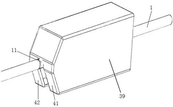
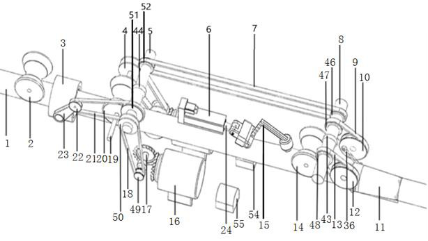
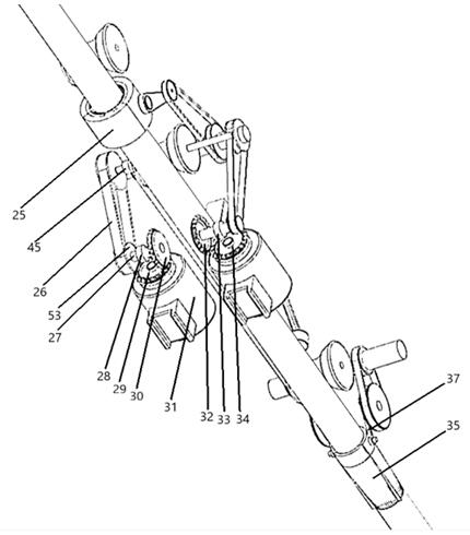
[0036] For the high-voltage line deicing device based on electric cylinder knocking in this embodiment, please refer to Figure 1-Figure 11 , including a box body 39 erected on the high-voltage line 1, a walking drive mechanism for driving the whole device to walk along the length direction of the high-voltage line 1, a cutting knife barrel mechanism for cutting ice on the surface of the high-voltage line 1, and a The knocking mechanism for knocking the ice on the high-voltage line, and the brush cleaning mechanism for cleaning the ice debris on the surface of the high-voltage line 1;

[0037] The specific structure of the walking driving mechanism: the walking driving mechanism includes a walking motor 31, and the walking motor 31 drives the walking driving wheel 20 to move along the length direction of the high-voltage line 1 through the walking transmission wheel assembly. The driven wheel 2, the driving wheel 20, the front driven wheel 14, and the rear driven wheel 2 are a...


PUM


Abstract

The invention relates to a high-voltage line deicing device based on electric cylinder knocking, and belongs to the technical field of high-voltage line deicing device structures. The deicing device comprises a box body erected on a high-voltage line; a walking driving mechanism used for driving the whole device to walk in the length direction of the high-voltage line, a cutting knife cylinder mechanism used for cutting ice covering the surface of the high-voltage line, a knocking mechanism used for knocking the ice covering the high-voltage line and a brush cleaning mechanism used for cleaning ice scraps on the surface of the high-voltage line are installed in the box body. The deicing device is ingenious in structural design, capable of effectively removing ice covering on the high-voltage line and high in snow removing efficiency and safety coefficient.

Description

technical field [0001] The invention relates to a high-voltage line deicing device based on electric cylinder knocking, and belongs to the technical field of high-voltage line deicing device structures. Background technique [0002] Transmission line deicing technology is divided into four categories: thermal melting method, mechanical deicing method, natural passive deicing method and other deicing methods. The above four deicing methods mainly have the following shortcomings: [0003] 1. The thermal deicing method is currently the most widely used anti-icing and deicing method. First, the "short-circuit deicing" scheme can realize remote deicing, but this technology is stretched when it is used for 500KV and above lines; the other is more used The current thermal ice melting method is a direct current ice melting technology. The disadvantage of this method is that the ice-coated line needs to be disconnected from the grid before melting the ice, and then the two wires are ...

Claims


Application Information

Patent Timeline
IPC IPC(8): H02G7/16
CPCH02G7/16
Inventor 张全忠封麟王建军王猛郝兴盛刘恩康
Owner LUDONG UNIVERSITY
Why Eureka
Try Eureka