Rotary mechanism and method for processing sheet metal parts

A technology of rotating mechanism and sheet metal parts, applied in metal processing mechanical parts, metal processing, metal processing equipment and other directions, can solve the problems of easy deviation of processing position and complicated operation, and achieve simple and convenient use process and small angle. Adjusting, avoiding loosening and shedding effects

Active Publication Date: 2021-06-04
常州市浩力电动工具有限公司
View PDF0 Cites 0 Cited by
  • Summary
  • Abstract
  • Description
  • Claims
  • Application Information

AI Technical Summary

Problems solved by technology

[0004] The purpose of the present invention is to solve the shortcomings in the prior art that the rotation of sheet metal parts during processing is mainly done manually, which makes the processing operation cumbersome and the processing position is prone to deviation, and proposes a sheet metal processing rotation institutions and their methods

Method used


Image

  • Rotary mechanism and method for processing sheet metal parts
  • Rotary mechanism and method for processing sheet metal parts
  • Rotary mechanism and method for processing sheet metal parts

Examples


Embodiment 1

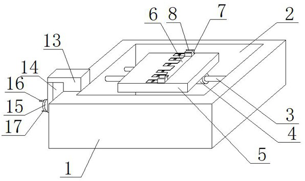
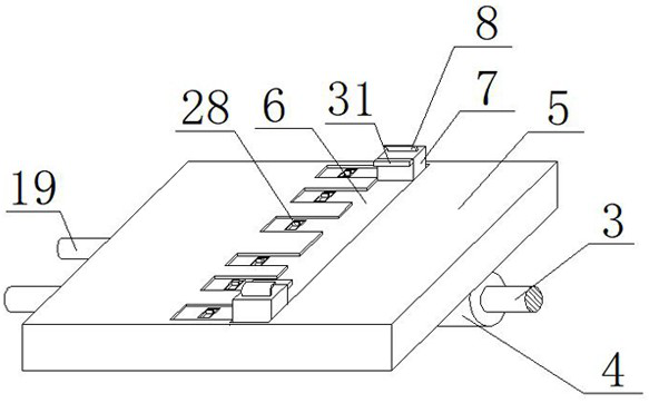
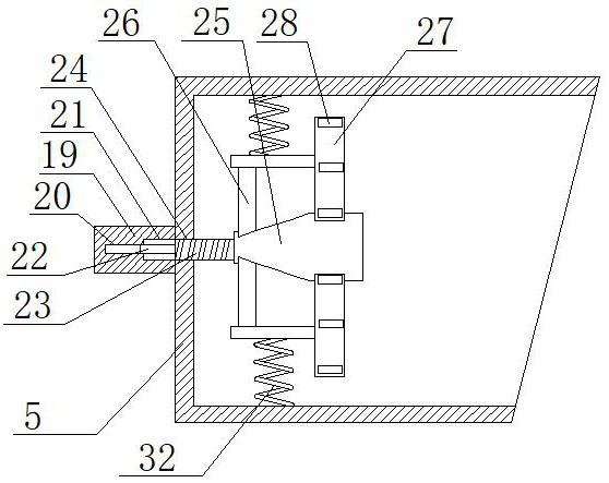
[0029] refer to Figure 1-6, a rotating mechanism for sheet metal parts processing, comprising a base plate 1, a movable groove 2 is provided on the base plate 1, a rotating column 3 is installed on the inner wall of the movable groove 2, and a fixed sleeve 4 is provided on the fixed sleeve of the rotating column 3, and the fixed sleeve 4 is fixedly installed with a rotating plate 5, the rotating plate 5 is a hollow structure, and the top of the rotating plate 5 is provided with a first chute 6, and two sliding seats 7 are slidably installed in the first chute 6, and the first chute 6 It is formed by connecting multiple slots together, including a long slot for moving the sliding seat 7 and several short slots for fixing the sliding seat 7, two sliding seats 7 are provided with splints 8, and one part of the bottom plate 1 One end of the rotating rod 10 is installed for side rotation, and the other end of the rotating rod 10 is fixedly equipped with a turntable 15, and a rocke...

Embodiment 2

[0039] refer to Figure 1-6 , a rotating mechanism for sheet metal parts processing, comprising a base plate 1, a movable groove 2 is provided on the base plate 1, a rotating column 3 is installed on the inner wall of the movable groove 2, and a fixed sleeve 4 is provided on the fixed sleeve of the rotating column 3, and the fixed sleeve 4 is welded with a rotating plate 5, the rotating plate 5 is a hollow structure, and the top of the rotating plate 5 is provided with a first chute 6, and two sliding seats 7 are slidably installed in the first chute 6, and the first chute 6 is A plurality of slots are connected together to form, including a long slot for moving the sliding seat 7 and several short slots for fixing the sliding seat 7, two sliding seats 7 are provided with splints 8, one side of the bottom plate 1 Rotate one end of the rotating rod 10, the other end of the rotating rod 10 is welded with a turntable 15, the turntable 15 is welded with a rocker 16, the rocker 16 ...


PUM


Abstract

The invention belongs to the technical field of sheet metal processing auxiliary equipment, in particular to a rotating mechanism and method for processing sheet metal parts, aiming at the fact that the rotation of the existing sheet metal parts during processing is mainly done manually, which makes the processing process cumbersome and difficult to process. The problem that the position is prone to deviation is now proposed as follows, which includes a bottom plate, a movable groove is opened on the bottom plate, a rotating column is installed on the inner wall of the movable groove, a fixed sleeve is set on the rotating column, and a rotating plate is installed on the fixed sleeve. There is a first chute on the top of the rotating plate, and two sliding seats are installed in the first chute, and splints are arranged on the two sliding seats. In the present invention, a turntable is set to cooperate with each structure to drive the sheet metal parts to rotate. In addition, a structure such as a knob is used to adjust the splint, so that the splint can better clamp the sheet metal, and when the turntable is turned, the turntable can also be rotated at a slower speed, which is suitable for rotation and adjustment of fine angles .

Description

technical field [0001] The invention relates to the technical field of sheet metal processing auxiliary equipment, in particular to a rotating mechanism for sheet metal processing and a method thereof. Background technique [0002] Sheet metal processing includes cutting, bending, punching, painting, etc. When cutting and punching, in the cutting device and punching device, the processing tools can only move on the plane, but cannot adjust the angle, so in the processing During the process, when the sheet metal part needs to be processed at a special angle, the sheet metal part needs to be rotated to complete operations such as oblique drilling and cutting. [0003] However, the existing sheet metal parts processing devices often do not have a device that can rotate the sheet metal parts. The rotation of the sheet metal parts is mostly done manually, which not only makes the rotation process cumbersome, but also easily causes deviations in the processing position. So just n...

Claims


Application Information

Patent Timeline
Patent Type & Authority Patents(China)
IPC IPC(8): B23Q3/06B23Q7/00
CPCB23Q3/06B23Q7/00
Inventor 平庆义
Owner 常州市浩力电动工具有限公司
Why Eureka
Try Eureka