Bearing outer wall machining equipment with feeding and discharging structure

A technology for processing equipment, feeding and discharging materials, applied in metal processing equipment, metal processing mechanical parts, manufacturing tools, etc., can solve the problems of complex processing structure, troublesome feeding and discharging, and low processing efficiency of milling machines.

Inactive Publication Date: 2021-01-26
杨正香
View PDF4 Cites 0 Cited by
  • Summary
  • Abstract
  • Description
  • Claims
  • Application Information

AI Technical Summary

Problems solved by technology

Some bearings will have a flat groove on the outer wall of one side of the outer ring, so that the top wire or the top can abut against the bottom surface of the groove on the outer wall of the outer ring to fix the bearing. The flat

Method used


Image

  • Bearing outer wall machining equipment with feeding and discharging structure
  • Bearing outer wall machining equipment with feeding and discharging structure
  • Bearing outer wall machining equipment with feeding and discharging structure

Examples


Embodiment Construction

[0021] The specific implementation manners of the present invention will be further described in detail below in conjunction with the accompanying drawings and embodiments. The following examples are used to illustrate the present invention, but are not intended to limit the scope of the present invention.

[0022] The following content reference Figure 1 to Figure 4 .

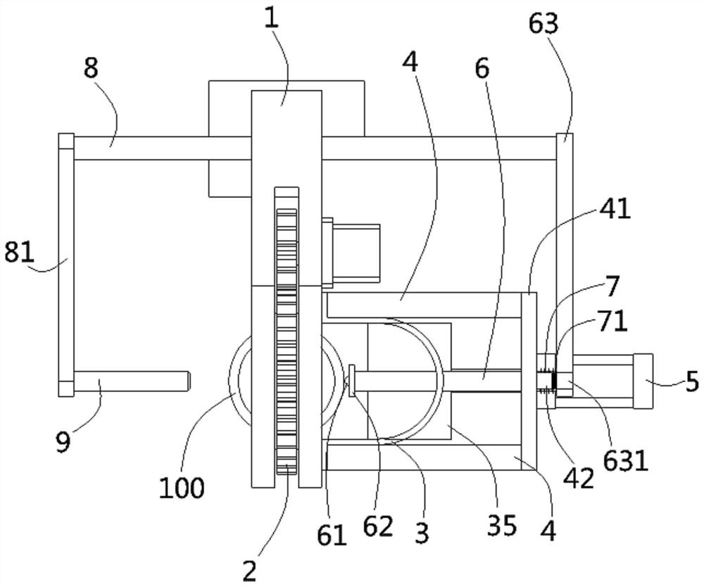
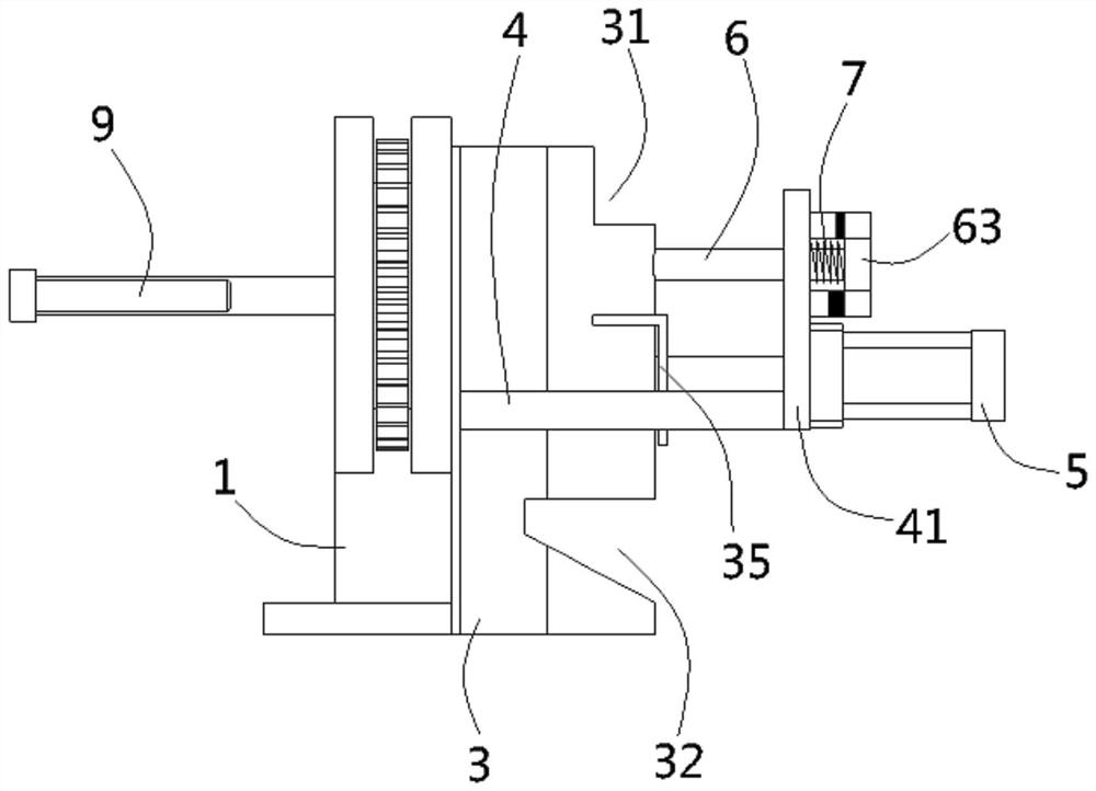
[0023] A kind of bearing outer wall processing equipment with a material inlet and outlet structure according to the present invention includes a headstock 1, a circular rotating seat 2 is provided at the front end of the headstock, and a bearing ring is formed inside the rotating seat. 100 matching positioning slots (not shown), a U-shaped material guide groove 3 is fixed on the headstock side wall on the right side of the swivel seat, the upper end of the material guide groove is formed with a feed port 31, and the lower end is formed with an oblique The discharge opening 32 of setting, the deflector plat...


PUM


Abstract

The invention discloses bearing outer wall machining equipment with a feeding and discharging structure. The bearing outer wall machining equipment comprises a lathe head base, a rotating base is arranged at the front end of the lathe head base, a U-shaped guide groove is fixed to the side wall of the lathe head base, a feeding port is formed in the upper end of the guide groove, a discharging port is formed in the lower end of the guide groove, and a supporting plate is fixed to the side wall of the guide groove and the lathe head base. A material supporting air cylinder is fixed to the supporting plate, and a bearing plate is fixed to a piston rod of the material supporting air cylinder. An ejector rod is inserted into the supporting plate, the right end of the ejector rod penetrates outof the supporting plate and is provided with a baffle in a formed mode, the ejector rod is sleeved with a compressed spring in an inserted mode, an upper support and a lower support are formed on thesupporting plate, an upper electromagnet is fixed to the upper support, and a lower electromagnet is fixed to the lower support. The electrified upper electromagnet and the electrified lower electromagnet can generate adsorption force and repulsive force on the baffle respectively, a guide rod is fixed to the baffle, a connecting rod is fixed to the guide rod, and a material returning rod is fixed to the connecting rod. Feeding and discharging of a bearing ring can be effectively achieved, and the bearing ring can be clamped and positioned.

Description

technical field [0001] The invention relates to the technical field of bearing processing equipment, in particular to a bearing outer wall processing equipment with a material inlet and outlet structure. Background technique [0002] Bearing is an important part of mechanical equipment. Its main function is to support the mechanical rotating body, reduce the friction coefficient during its movement, and ensure its rotation accuracy. Some bearings will have a flat groove on the outer wall of one side of the outer ring, so that the top wire or the top can abut against the bottom surface of the groove on the outer wall of the outer ring to fix the bearing. The flat groove of the existing bearing outer ring is generally processed by a milling machine However, the milling machine is used to process complex structures, troublesome feeding and discharging materials, and low processing efficiency. Contents of the invention [0003] The purpose of the present invention is to solve...

Claims


Application Information

Patent Timeline
IPC IPC(8): B23G1/32B23G11/00B23Q11/00B23Q11/08
CPCB23G1/32B23G11/00B23Q11/0042B23Q11/08
Inventor 杨正香
Owner 杨正香
Why Eureka
Try Eureka