
Single-cylinder multi-point hot runner system

A hot runner and multi-point technology, applied in the field of single-cylinder multi-point hot runner system, can solve the problems of poor blade rotation balance, affecting the overall structure of the fan blade, and unable to ensure synchronization, etc., to achieve high de-balancing requirements, uniform quality, The effect of uniform and fast feeding speed

Inactive Publication Date: 2020-04-21
FRENK HOT RUNNER TECH CO LTD
View PDF5 Cites 0 Cited by
  • Summary
  • Abstract
  • Description
  • Claims
  • Application Information

AI Technical Summary

Problems solved by technology

It is the main molding equipment for making thermoplastics or thermosetting plastics into various shapes of plastic products using injection molds. Products with a circular or centrally symmetrical divergent structure, such as fan pages, either have surface finish requirements, Either it is necessary to set up a transmission structure, so the injection hole cannot be set in the center of the product. When these products are injection molded, the glue feeding speed in all directions needs to be uniform and fast, so that the injection molding raw materials can be quickly and symmetrically distributed on the circumference or surrounding divergent structures. It is only the product that can meet the requirements of dynamic balance and static balance. The current injection molding machine cannot guarantee synchronization due to multiple needle valve drives, and the molding quality of each blade of the fan blade cannot be guaranteed to be consistent. This will affect the overall structure of the fan blade, resulting in poor rotational balance

Method used


Image

  • Single-cylinder multi-point hot runner system
  • Single-cylinder multi-point hot runner system
  • Single-cylinder multi-point hot runner system

Examples


Embodiment Construction

[0027] The technical solutions of the present invention will be further described below in conjunction with the accompanying drawings and through specific implementation methods.

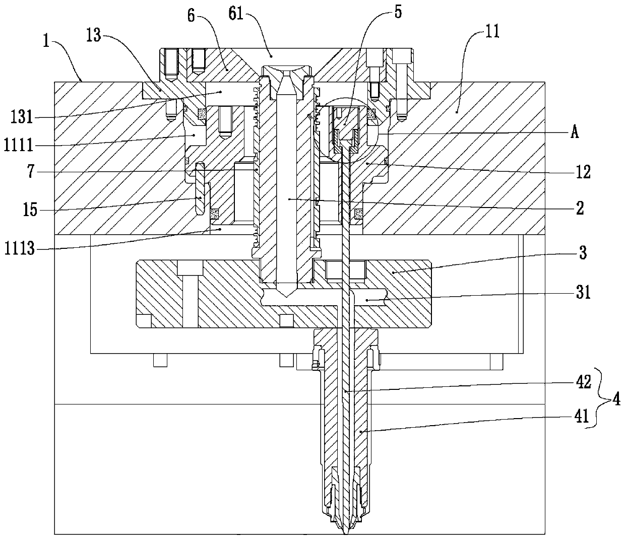
[0028] A single-cylinder multi-point hot runner system in this embodiment is used for injection molding of products with a circular or centrally symmetrical structure that diverges outward, such as figure 1 As shown, it includes an annular cylinder 1, a feed nozzle 2, a splitter plate 3 and a needle valve 4; the annular cylinder 1 includes a cylinder body 11, an annular piston 12, and an end cover 13, wherein:

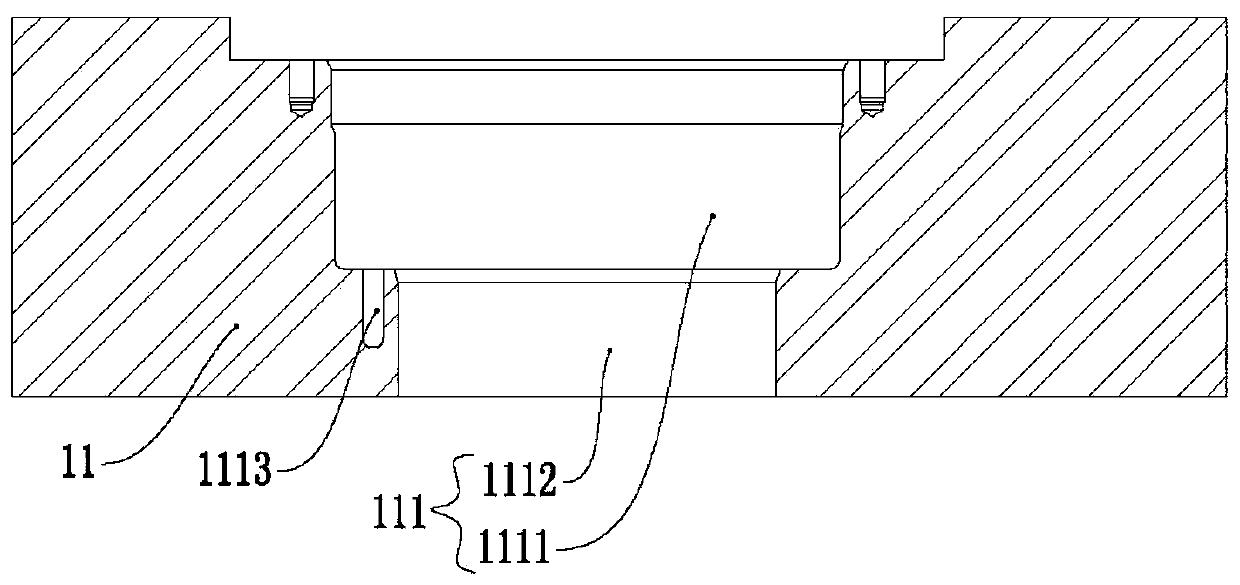
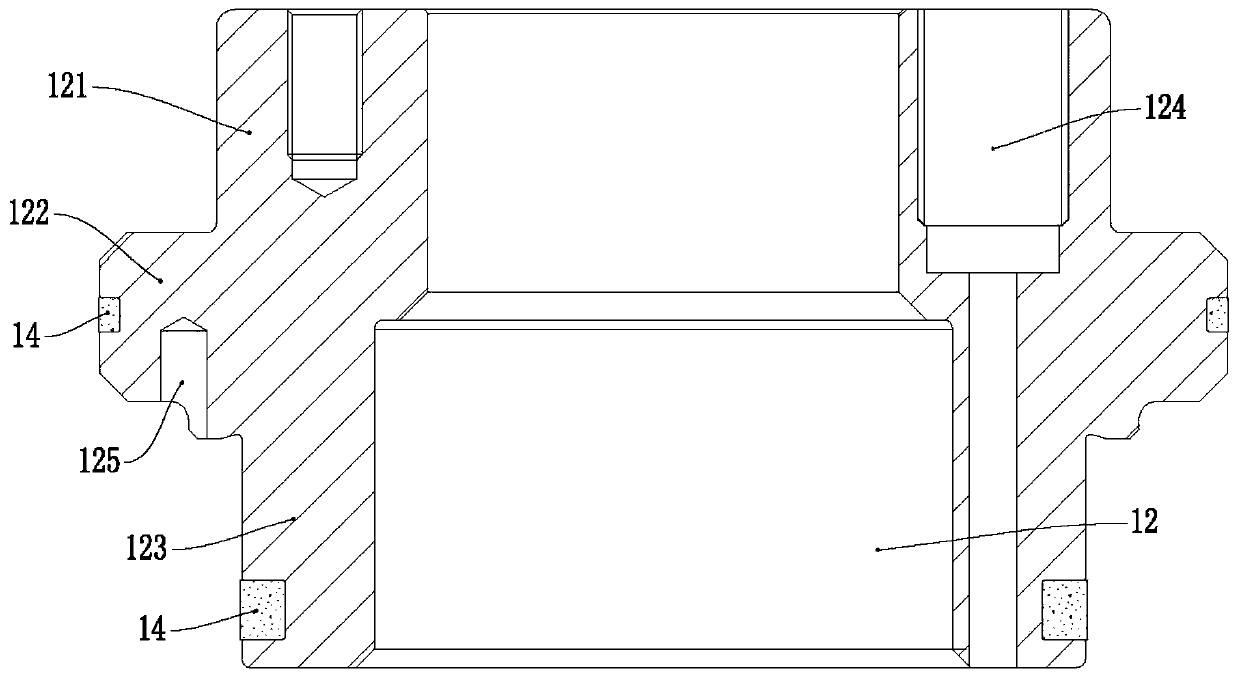
[0029] A cavity 111 is provided inside the cylinder body 11, and the annular piston 12 is disposed in the cavity 111;

[0030] The annular piston 12 is slidingly fitted with the inner wall of the cavity, and the annular piston 12 divides the cavity into two upper and lower airtight air cavities;

[0031] The end cover 13 is provided at the opening of the cavity 111, and the end cover 13 is ...


PUM


Abstract

The invention discloses a single-cylinder multi-point hot runner system, which is characterized in that a cavity is formed in a cylinder body, and an annular piston is arranged in the cavity; the annular piston is in sliding fit with the inner wall of an accommodating cavity and divides the accommodating cavity into an upper annular air cavity and a lower annular air cavity which are sealed respectively; an end cover is arranged at the opening of the cavity and is in sealed connection with the inner wall of the cavity; hot runners which are communicated with one another are arranged in a flowdividing plate, and the flow dividing plate is arranged below the cylinder body; a feeding nozzle is connected with the flow dividing plate, and an internal runner of the feeding nozzle is communicated with an inlet of each hot runner; a plurality of needle valves are arranged, each needle valve comprises a valve body and a valve needle; the upper end of the valve body is connected with the flow dividing plate, an internal runner of the valve body is communicated with the hot runner, and the valve bodies are uniformly arranged around the central axis of the annular piston; the upper end of thevalve needle is connected with the annular piston, and the lower end is inserted into the valve body; the lower end of the needle valve is connected with a pouring gate of the mold, and the valve needle is used for controlling opening and closing of the needle valve. According to the invention, the opening and closing of the needle valves can be synchronously controlled, so that the dynamic balance performance of an injection molding product is enabled to be higher.

Description

technical field [0001] The invention relates to the technical field of injection molding equipment, in particular to a single-cylinder multi-point hot runner system. Background technique [0002] Injection molding machine is also known as injection molding machine or injection machine. It is the main molding equipment for making thermoplastics or thermosetting plastics into various shapes of plastic products using injection molds. Products with a circular or centrally symmetrical divergent structure, such as fan pages, either have surface finish requirements, Either it is necessary to set up a transmission structure, so the injection hole cannot be set in the center of the product. When these products are injection molded, the glue feeding speed in all directions needs to be uniform and fast, so that the injection molding raw materials can be quickly and symmetrically distributed on the circumference or surrounding divergent structures. It is only the product that can meet ...

Claims


Application Information

Patent Timeline
IPC IPC(8): B29C45/28B29C45/27
CPCB29C45/2806B29C45/2725B29C2045/2893
Inventor 王桂林
Owner FRENK HOT RUNNER TECH CO LTD
Learn More