Pulley block

A pulley block and pulley technology, applied in portable lifting devices, winch devices, etc., can solve the problems of slider damage, difficulty in cleaning debris, debris stuck, etc., and achieve the effect of convenient use and not easy to hide dirt and evil people and practices

Pending Publication Date: 2020-04-21
东莞市沃尔泰克地毯机械设备有限公司
View PDF0 Cites 0 Cited by
  • Summary
  • Abstract
  • Description
  • Claims
  • Application Information

AI Technical Summary

Problems solved by technology

[0003] The vertical carpet machine is easily blocked by debris (fine pile or debris, etc.) generated during the weaving process of the carpet machine. It is generally supported by a slider that controls lateral movement, and the slider that supports the carpet machine is in the sliding process. , it is easy to get debris stuck in the ball of the slider, which will damage the slider. Once the slider is blocked, because the structure of the slider is relatively closed, it is difficult to clean up the debris, which will affect the normal operation of the entire carpet machine.

Method used


Image

  • Pulley block
  • Pulley block
  • Pulley block

Examples


Embodiment 1

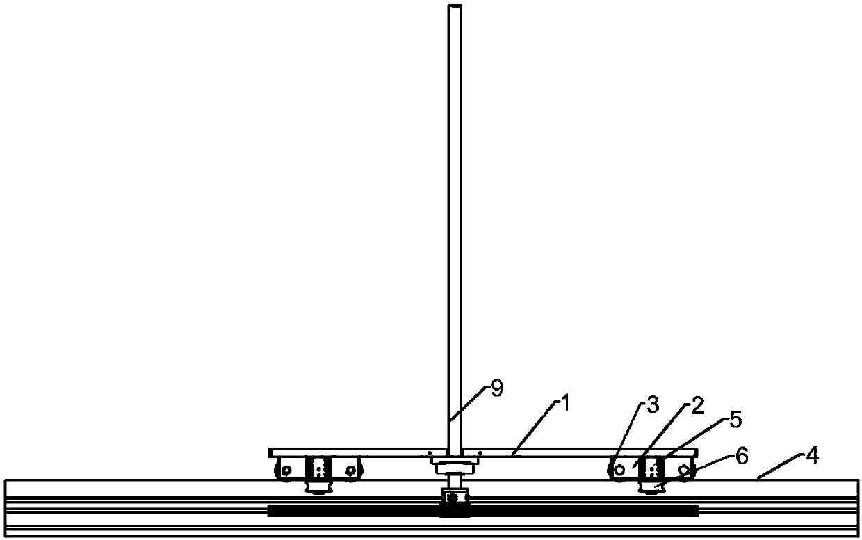
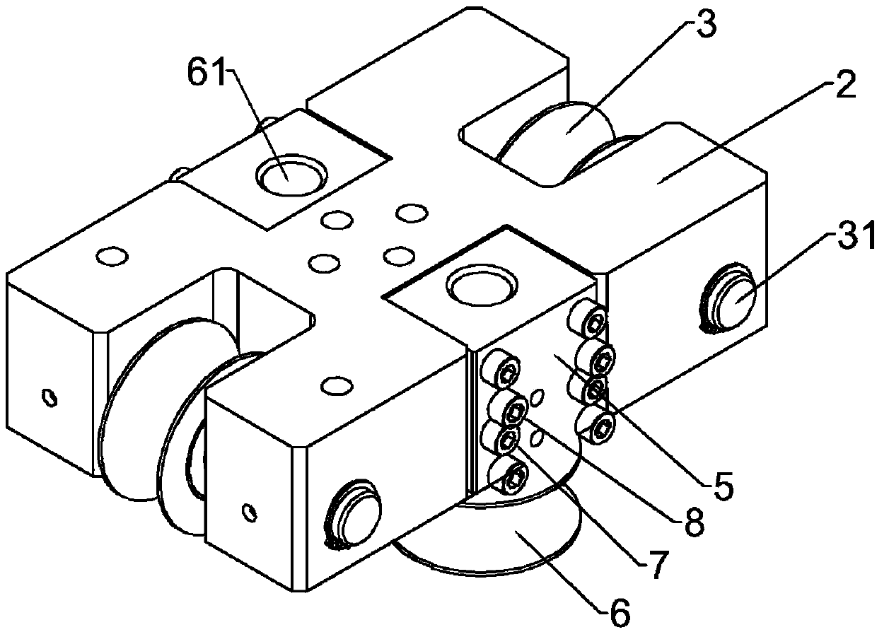
[0018] Example 1: Please refer to Figure 1-3 , a pulley block, including a pulley fixing frame 2 fixed on the left and right sides below the fixing plate 1, the left and right sides of the pulley fixing frame 2 are horizontally symmetrically rotated and connected with a longitudinal pulley 3, and the longitudinal pulley 3 is slidingly connected to the metal guide rail 4 , the front and rear sides of the pulley holder 2 are fixedly connected with a pulley adjustment block 5 that is adjustable in the vertical direction relative to the metal guide rail 4, and the pulley adjustment block 5 is rotatably connected with a horizontal pulley 6 that is slidably matched with the metal guide rail 4 through a lateral bearing 61.

[0019] The pulley adjustment blocks 5 on the front and rear sides are symmetrical to each other.

[0020] The longitudinal pulley 3 is rotatably connected through a longitudinal bearing 31 passing through the pulley fixing frame 2 .

[0021] A drive shaft 9 is ...

Embodiment 2

[0022] Embodiment 2: The difference between this embodiment and the previous embodiment is that the pulley adjusting block 5 is connected with the pulley fixing frame 2 through the fixing screw 7 threadedly connected with the pulley fixing frame 2, and the pulley adjusting block 5 slides relative to the fixing screw 7 Connection, the top surface screw 8 is threaded on the pulley adjustment block 5, and the top surface screw 8 offsets against the outer surface of the pulley holder 2. In this embodiment, an adjustment structure of the pulley adjustment block 5 is specifically given, which is simpler and more convenient to adjust the pulley adjustment block 5. In addition, the pulley adjustment block can also be adjusted by other adjustment methods, such as the pulley adjustment block 5 Be connected with bolt rotation, and the mode that bolt inner end is threaded with pulley fixed frame 2 also can.

[0023] Among them, the adjustment principle of the fixing screw 7 and the top sc...


PUM


Abstract

The invention discloses a pulley block, and belongs to the field of pulleys. The pulley block comprises pulley fixing frames fixed to the left side and the right side below a fixing plate, longitudinal pulleys are symmetrically and rotationally connected to the left side and the right side of each pulley fixing frame in the horizontal direction, and the longitudinal pulleys are slidably connectedwith a metal guide rail, the front side and the rear side of the pulley fixing frame are fixedly connected with pulley adjusting blocks adjustable relative to the vertical direction of the metal guiderail, and the pulley adjusting blocks are rotationally connected with transverse pulleys in sliding fit with the metal guide rail through transverse bearings. Compared with the prior art, the pulleyblock has the beneficial effects that the pulley block can be freely disassembled and assembled, and the pulley with the U-shaped design is not prone to hiding dirt; and when the pulley is blocked bysundries, the transverse pulleys can be detached to clean the sundries, so that the use is more convenient.

Description

technical field [0001] The invention relates to the field of pulleys, in particular to a pulley block. Background technique [0002] A pulley is a small wheel with grooves around it that can rotate around an axis. A simple machine that can rotate around a central axis, consisting of a grooved disc that can rotate around a central axis and a cable that spans the disc, is called a pulley. [0003] The vertical carpet machine is easily blocked by debris (fine pile or debris, etc.) generated during the weaving process of the carpet machine. It is generally supported by a slider that controls lateral movement, and the slider that supports the carpet machine is in the sliding process. , It is easy to get debris stuck in the ball of the slider, which will damage the slider. Once the slider is blocked, because the structure of the slider is relatively closed, it is difficult to clean up the debris, which will affect the normal operation of the entire carpet machine. [0004] For t...

Claims


Application Information

Patent Timeline
Patent Type & Authority Applications(China)
IPC IPC(8): B66D3/06
CPCB66D3/06
Inventor 刘安全
Owner 东莞市沃尔泰克地毯机械设备有限公司
Why Eureka
Try Eureka