Dynamic tool tip position calibration method and system based on optical locator, medium and equipment

A technology of optical positioning and dynamic calibration, which is applied in the field of optical locator, can solve the problems of complex calibration device, difficulty in guaranteeing machining accuracy, and affecting engineering calculation accuracy, etc., and achieve the effects of avoiding technical defects, convenient calibration operation, and reasonable design

Inactive Publication Date: 2020-04-21
上海嘉奥信息科技发展有限公司
View PDF6 Cites 1 Cited by
  • Summary
  • Abstract
  • Description
  • Claims
  • Application Information

AI Technical Summary

Problems solved by technology

However, machining accuracy is sometimes difficult to guarantee. At this time, the actual offset of the tip cannot be guaranteed, which affects the accuracy of engineering calculations.
[0003] Patent document CN205215354U discloses a tip calibration method, the calibration de

Method used


Image

  • Dynamic tool tip position calibration method and system based on optical locator, medium and equipment
  • Dynamic tool tip position calibration method and system based on optical locator, medium and equipment
  • Dynamic tool tip position calibration method and system based on optical locator, medium and equipment

Examples


Example Embodiment

[0032] The present invention will be described in detail below in conjunction with specific embodiments. The following examples will help those skilled in the art to further understand the present invention, but do not limit the present invention in any form. It should be noted that for those of ordinary skill in the art, several changes and improvements can be made without departing from the concept of the present invention. These all belong to the protection scope of the present invention.
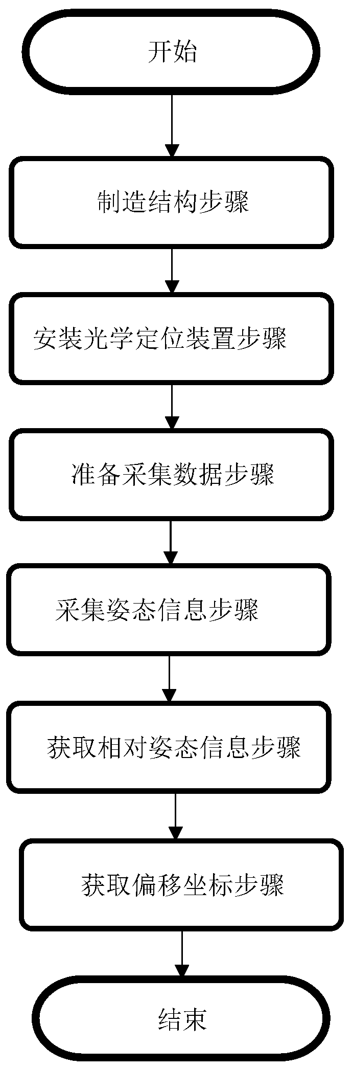
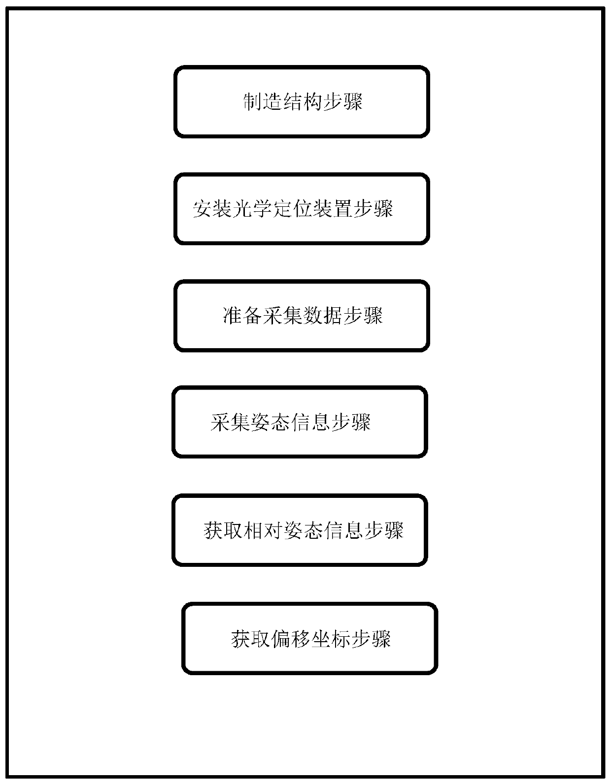
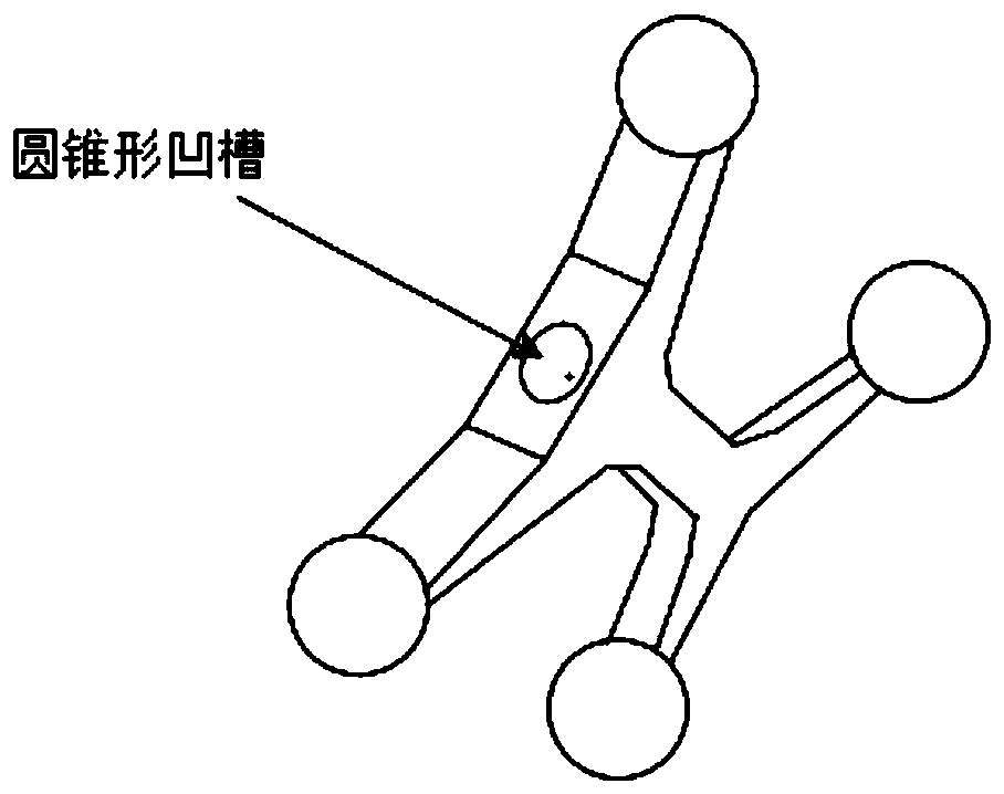
[0033] Such as figure 1 , figure 2 , image 3 , Figure 4 As shown, a method for dynamically calibrating the position of a tool tip based on an optical positioner according to the present invention includes: manufacturing structure steps: manufacturing a specific tool tip and reference block structure; installing an optical positioning device: on a specific surface of the reference block Open a conical groove in the position, and install an optical positioning device at a specific positi...


PUM


Abstract

The invention provides a dynamic tool tip position calibration method and system based on an optical locator, a medium and equipment. The method comprises the steps of constructing a structure; mounting an optical positioning device by forming a conical groove in a specific surface position of a reference block, and mounting the optical locater in a specific position; preparing for data collectionby tightly jacking the tool tip against the groove of the reference positioning block, and preparing to acquire data; acquiring attitude information by rotating a tool around the tool tip , and acquiring the attitude information of the tool and the attitude information of the reference positioning block through the optical locator; and acquiring relative attitude information by transmitting the acquired information to a conversion algorithm, transmitting the attitude information of the tool relative to the reference positioning block into a spherical fitting algorithm, and obtaining the offset coordinates of the tool tip phase under a tool coordinate system. According to the invention, the purpose of obtaining accurate tool tip offset data can be achieved, and meanwhile calibration operation becomes more convenient.

Description

technical field [0001] The present invention relates to the field of optical locators, in particular to a dynamic calibration method, system, medium and equipment based on the position of the tip of a tool based on the optical locator. Background technique [0002] The offset data of the tool tip is an important data commonly used in engineering calculations. The accuracy of the offset data of the tool tip will directly determine the accuracy of the engineering calculation. Typically, the source of the offset for the tip position is the engineering drawing, but the actual offset depends on machining accuracy. However, machining accuracy is sometimes difficult to guarantee. At this time, the actual offset of the tip cannot be guaranteed, which affects the accuracy of engineering calculations. [0003] Patent document CN205215354U discloses a tip calibration method, the calibration device of this method is very complicated, the machining accuracy is difficult to guarantee, a...

Claims


Application Information

Patent Timeline
IPC IPC(8): G01B11/00
CPCG01B11/002
Inventor 肖建如吕天予周振华马科威刘铁龙矫健曹佳实
Owner 上海嘉奥信息科技发展有限公司
Why Eureka
Try Eureka