
Line laser sensor space pose calibration piece and calibration method

A pose calibration and sensor technology, applied in the direction of instruments, optical devices, measuring devices, etc., can solve the problems of guaranteeing the processing accuracy of key geometric features and the difficulty of processing acceptance, and achieves simple and easy calibration operation, accurate calibration, and simple structure Effect

Active Publication Date: 2021-09-07
BEIJING UNIV OF TECH
View PDF14 Cites 0 Cited by
  • Summary
  • Abstract
  • Description
  • Claims
  • Application Information

AI Technical Summary

Problems solved by technology

However, the calibration method based on the standard mandrel requires multiple fitting operations of small sample data and multiple linear movements of the sensor, which introduces the superposition of multi-source errors; the calibration method based on special calibration parts with complex geometric features, It brings great challenges to the processing of calibration parts, and brings great difficulties to the processing accuracy guarantee and processing acceptance of key geometric features.

Method used


Image

  • Line laser sensor space pose calibration piece and calibration method
  • Line laser sensor space pose calibration piece and calibration method
  • Line laser sensor space pose calibration piece and calibration method

Examples


Embodiment Construction

[0028] The present invention is described below in conjunction with concrete processing example:

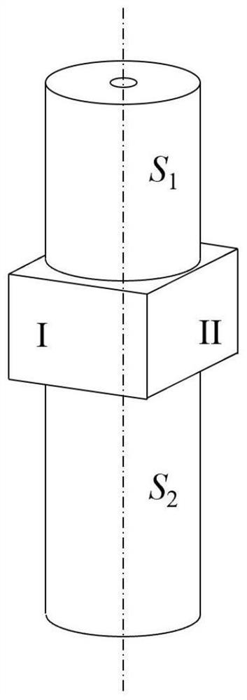
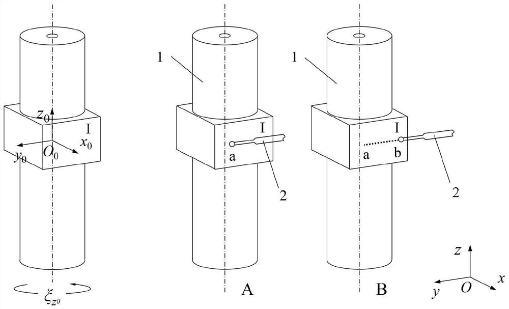
[0029] The line laser sensor space pose calibration part involved in the present invention, such as figure 1 As shown, on the basis of a standard mandrel, a cuboid metal block is arranged in the middle of the axis, and a tapered hole is provided in the center of the upper and lower end faces of the standard mandrel for fixing. The upper shaft section S1 and the lower shaft section S2 of the standard mandrel part of the calibration piece require both coaxiality and cylindricity to be 1 μm. The cuboid metal block has strict requirements only on two adjacent planes I and II. The perpendicularity between plane I and plane II is 1 μm, and the parallelism between plane I and plane II and the axis of the standard mandrel is 1 μm.

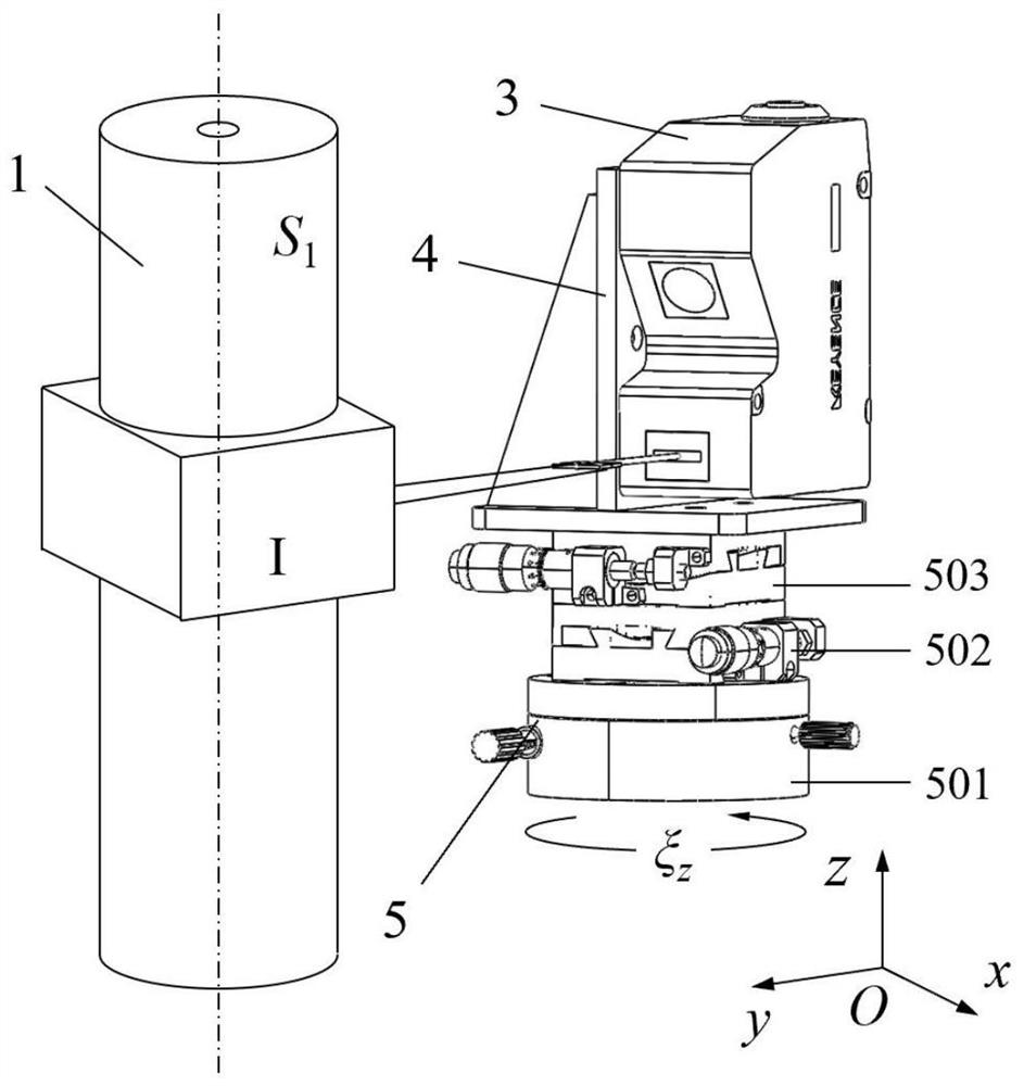
[0030] The line laser sensor 3 is connected with the three-dimensional angle micro-motion platform 5 through the connecting mechanism 4. The three-dimension...


PUM


Abstract

The invention discloses a line laser sensor space pose calibration piece and a calibration method, which combine the advantages of gear measurement center contact measurement and a simple geometric feature calibration piece, and realize accurate calibration of a line laser sensor through simple and easy calibration operation. On the basis of a standard mandrel, a cuboid metal block is arranged in the middle of the axis, and the centers of the upper end face and the lower end face of the standard mandrel are each provided with a conical hole for fixing. The coaxiality and cylindricity of an upper shaft section S1 and a lower shaft section S2 of a standard core shaft part of the calibration piece are required to be 1 [mu]m. The perpendicularity of the plane I and the plane II is 1 [mu]m, and the parallelism of the plane I and the plane II and the axis of the standard mandrel is 1 [mu]m. The calibration piece is simple in structure, the existing manufacturing process can meet the machining requirement of high-precision geometrical characteristics, the calibration piece is combined with the advantage of gear measurement center contact type measurement, calibration operation is simple and easy to implement, and accurate calibration of the line laser sensor can be achieved.

Description

technical field [0001] The invention relates to a space pose calibration part and a calibration method of a line laser sensor, in particular to a space pose calibration part and a calibration method of a line laser sensor based on a gear measurement center, belonging to the field of precision measurement. Background technique [0002] The line laser sensor is widely used in the field of laser triangulation measurement. It can obtain the distance between the zero plane of the sensor beam and the surface of the measured object in real time within a certain range. It is a non-contact measurement with fast, high precision, high Efficiency, convenient operation and so on. The many advantages of the line laser sensor facilitate industrial applications, and its high packaging reduces the technical requirements for operators, making it easier and more convenient to achieve precise measurement of the measured object. [0003] Before precise measurement, it is particularly important ...

Claims


Application Information

Patent Timeline
IPC IPC(8): G01B11/00
CPCG01B11/002
Inventor 石照耀孙衍强于渤
Owner BEIJING UNIV OF TECH
Learn More