Intrusion detection equipment convenient to mount or dismount
An intrusion detection and easy installation technology, applied in the field of detection, can solve the problems of inconvenient installation, difficult to apply around the wall, difficult installation and disassembly, etc., to achieve the effect of improving service life
- Summary
- Abstract
- Description
- Claims
- Application Information
AI Technical Summary
Problems solved by technology
Method used
Image
Examples
Embodiment 1
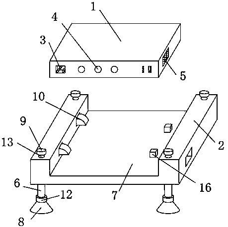
[0021] Such as figure 1 As shown, an embodiment provided by the present invention is an intrusion detection device that is easy to install and disassemble, including a housing 1 and a mounting base 2, a power port 3 is provided on the left side of the front end of the housing 1, and a An infrared sensor head 4 is provided in the middle, a cooling hole 5 is provided in front of the right end of the housing 1, an open groove 7 is provided in the middle of the upper end of the mounting base 2, and sleeves 6 are provided at the four corners of the lower end of the mounting base 2. The bottom of the tube 6 is provided with a fixed disc 12, and an air sucker 8 is provided under the fixed disc 12. An adjustable fixed block 9 is provided on the upper end surface of the mounting seat 2 corresponding to the position of the casing 6, and the inner wall of one side of the open groove 7 is provided with a For the two limit blocks 10 , the mounting base 2 is provided with an adjustment rod ...
Embodiment 2
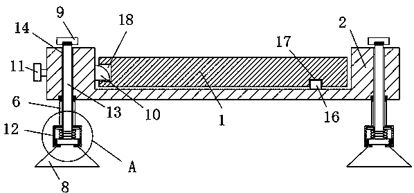
[0023] On the basis of Example 1, such as figure 2 As shown, an embodiment provided by the present invention: the top of the casing 6 is connected to the mounting seat 2 through threads, the adjustable pressure rod 13 is arranged inside the casing 6, and the four corners of the mounting seat 2 are provided with circular grooves corresponding to the pressure rod 13 14. The head of the pressure rod 13 passes through the circular groove 14 and is connected to the bottom of the fixed block 9. The head of the pressure rod 13 is connected to the fixed block 9 through threads. There are two blocks 16 on the right side of the bottom of the open groove 7. The housing 1. A rectangular slot 17 is provided on the lower end surface corresponding to the clamping block 16, and a limiting slot 18 is provided on one side of the housing 1 corresponding to the position of the limiting block 10.
Embodiment 3
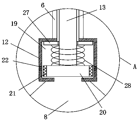
[0025] On the basis of embodiment 1 and embodiment 2, as image 3 As shown, an embodiment provided by the present invention: the tail of the pressure rod 13 reaches the fixed disc 12, the fixed disc 12 is provided with a mounting groove 19, the tail of the pressure rod 13 reaches the bottom of the mounting groove 19 and is provided with a sealing disc 20 , the outer ring of the sealing disc 20 is provided with a gasket 21, the inner wall of the installation groove 19 is provided with a number of ventilation holes 22 at the position corresponding to the outer ring of the sealing disc 20, and the outer ring of the pressure rod 13 is provided with a fixing plate 27 at the top of the installation groove 19, The outer ring of the pressure rod 13 is provided with a secondary spring 28 at a position between the fixed plate 27 and the sealing disc 20 , and an opening is provided at the bottom of the mounting groove 19 to connect with the air sucker 8 .
PUM
 Abstract
Description
Claims
Application Information
 - R&D
- Intellectual Property
- Life Sciences
- Materials
- Tech Scout
- Unparalleled Data Quality
- Higher Quality Content
- 60% Fewer Hallucinations
Browse by: Latest US Patents, China's latest patents, Technical Efficacy Thesaurus, Application Domain, Technology Topic, Popular Technical Reports.
© 2025 PatSnap. All rights reserved.Legal|Privacy policy|Modern Slavery Act Transparency Statement|Sitemap|About US| Contact US: help@patsnap.com


