Eureka AIR delivers breakthrough ideas for toughest innovation challenges, trusted by R&D personnel around the world.

Method and system for quickly positioning optical cable interruption position

An optical cable and fast technology, which is applied in the field of rapid positioning of optical cable interruption positions, can solve the problems that the geographical location of optical cable interruption points cannot be well determined, and consume a lot of manpower and time, so as to improve the efficiency of investigation work, improve work reliability, The effect of facilitating the promotion of the application

Inactive Publication Date: 2020-04-21
GUANGDONG POWER GRID CO LTD +1
View PDF4 Cites 4 Cited by
  • Summary
  • Abstract
  • Description
  • Claims
  • Application Information

AI Technical Summary

Problems solved by technology

[0005] (2) Positioning by optical time domain reflectometer OTDR can only determine the length of the optical cable where the optical cable is interrupted
It is impossible to judge the geographical location of the specific cable interruption point very well
As a result, it is necessary to compare the length of the cable interruption position with the specific geographical location to determine a relatively long-distance inspection area. In this inspection area, the optical cables of each cable shaft or tower are often checked one by one. This inspection takes a lot of time. big manpower and time

Method used


Image

  • Method and system for quickly positioning optical cable interruption position
  • Method and system for quickly positioning optical cable interruption position

Examples


Embodiment 1

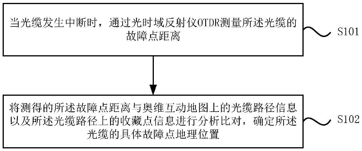
[0030] See attached figure 1 , Is a schematic flowchart of a method for quickly locating the interruption position of an optical cable according to Embodiment 1 of the present invention. By adopting this positioning method, one is to reduce the range of the optical cable interruption position to a small area, and the other is to allow operation and maintenance personnel who are not familiar with the optical cable path to quickly reach the optical cable interruption area, and the operation and maintenance personnel can also pass through the Austrian The street view pictures of the Dimension Interactive Map can accurately compare the specific geographic location. Make the inspection of the cable interruption location fast and efficient. The method specifically includes the following steps:

[0031] S101: When the optical cable is interrupted, measure the distance to the fault point of the optical cable by using an optical time domain reflectometer OTDR;

[0032] S102. Analyze and c...

Embodiment 2

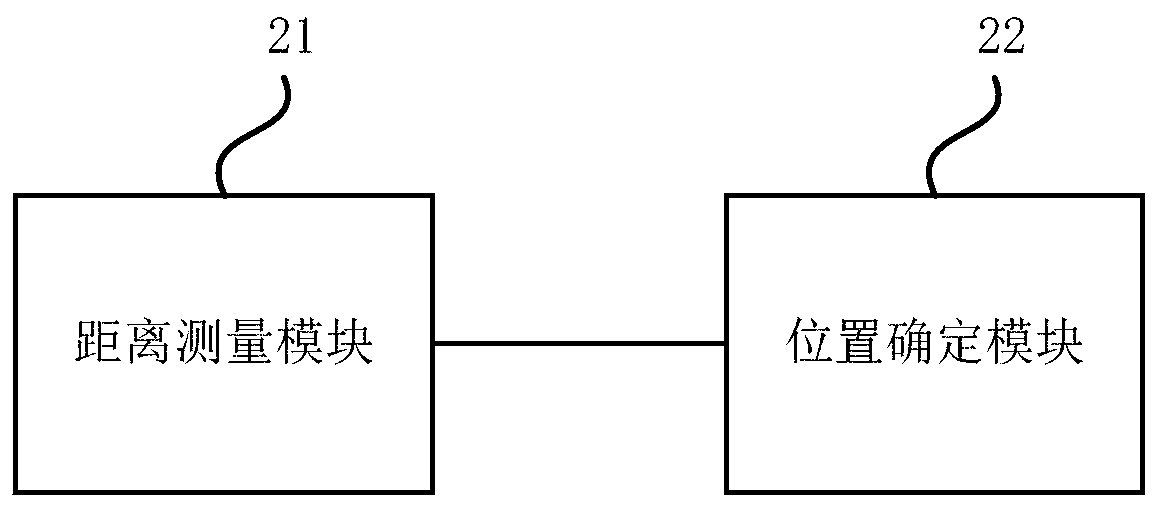
[0040] Please refer to figure 2 , The second embodiment of the present invention provides a system for quickly locating the interruption position of an optical cable, and the system includes:

[0041] The distance measurement module 21 is used to measure the distance to the fault point of the optical fiber cable through an optical time domain reflectometer OTDR when the optical cable is interrupted;

[0042] The position determining module 22 is used to analyze and compare the measured distance of the fault point with the optical cable path information on the Aowei interactive map and the collection point information on the optical cable path to determine the specific fault point geographic location of the optical cable position.

[0043] Preferably, the system for quickly locating the interruption position of the optical cable further includes:

[0044] The operation and maintenance notification module is used to analyze and compare the measured distance of the fault point with the...


PUM


Abstract

The invention discloses a method and system for quickly positioning an optical cable interruption position. The method comprises the steps: measuring the fault point distance of an optical cable through an OTDR (Optical Time Domain Reflectometer) when the optical cable is interrupted; and analyzing and comparing the measured fault point distance with the optical cable path information on the Oldham interactive map and the collection point information on the optical cable path, and determining the specific fault point geographic position of the optical cable. According to the method and systemfor quickly positioning the optical cable interruption position, the position range of optical cable interruption is narrowed, the speed of operation and maintenance personnel reaching the vicinity ofthe optical cable interruption position is increased, the troubleshooting work efficiency of the optical cable interruption position is improved, the operation risk is reduced, the work reliability is improved, and popularization and application are facilitated.

Description

Technical field [0001] The invention relates to the technical field of optical cable fault inspection and repair, and in particular to a method and system for quickly locating the interruption position of an optical cable. Background technique [0002] At present, the information transmission of China Southern Power Grid is based on optical communication. The basis of optical communication is optical cable. Optical cables laid in outdoor cable trenches or on poles and towers are easily damaged by various factors, such as human factors (municipal construction excavation, stolen cutting, etc.), natural disasters (such as landslides, landslides, floods, etc.). Once the optical cable is damaged and the optical cable is interrupted, it will seriously affect the safe operation of the optical cable. Operation and maintenance personnel need to quickly repair the interrupted optical cable. In the process of fiber optic cable repair, it is particularly critical to quickly locate the locat...

Claims


Application Information

Patent Timeline
Patent Type & Authority Applications(China)
IPC IPC(8): H04B10/071
CPCH04B10/071
Inventor 吴一帆刘友好李伟龙
Owner GUANGDONG POWER GRID CO LTD
Why Eureka
Eureka Blog
Learn More