


Quick Research
Generate reliable direction feasibility study reports for your R&D in just a few steps.

Technical Q&A
Discover and master advanced knowledge NOW. Basics, ideas, possibilities, all at once.

Find Solutions
As an expert in R&D theories, this can generate solutions to your technical problems instantly.

Evaluate Feasibility
Analyze your overall solution with one click, know your potential R&D risks in advance.

Monitor Landscape
Get weekly tech updates, stay abreast of the latest tech innovations and key insights.
Transport device and transport method
A technology of handling devices and trolleys, which is applied to storage devices, transportation and packaging, and lifting equipment in mines, etc. It can solve problems such as cargo collapse, box swing, and collision with box walls to improve operability and safety. Effect
- Summary
- Abstract
- Description
- Claims
- Application Information
AI Technical Summary
Problems solved by technology
Method used
Image

Examples
no. 1 approach
[0053] (The overall structure of the transport device)
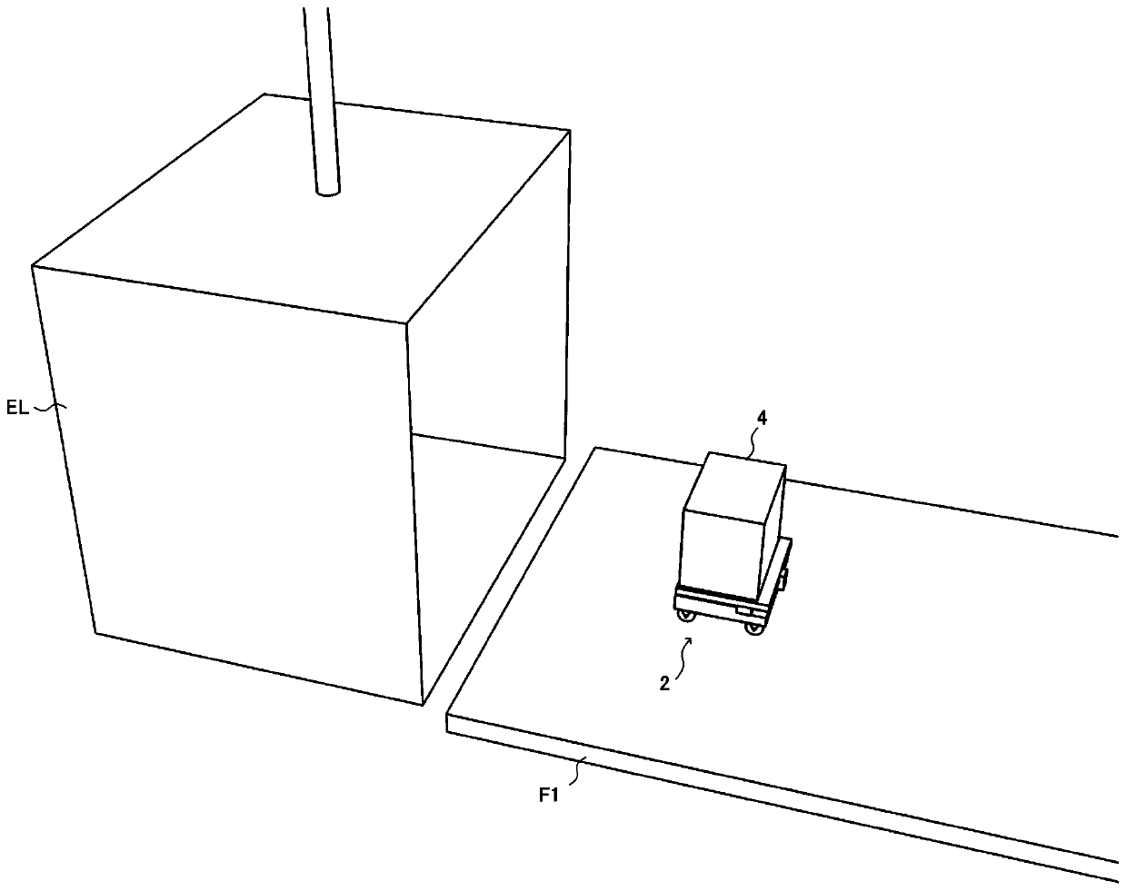
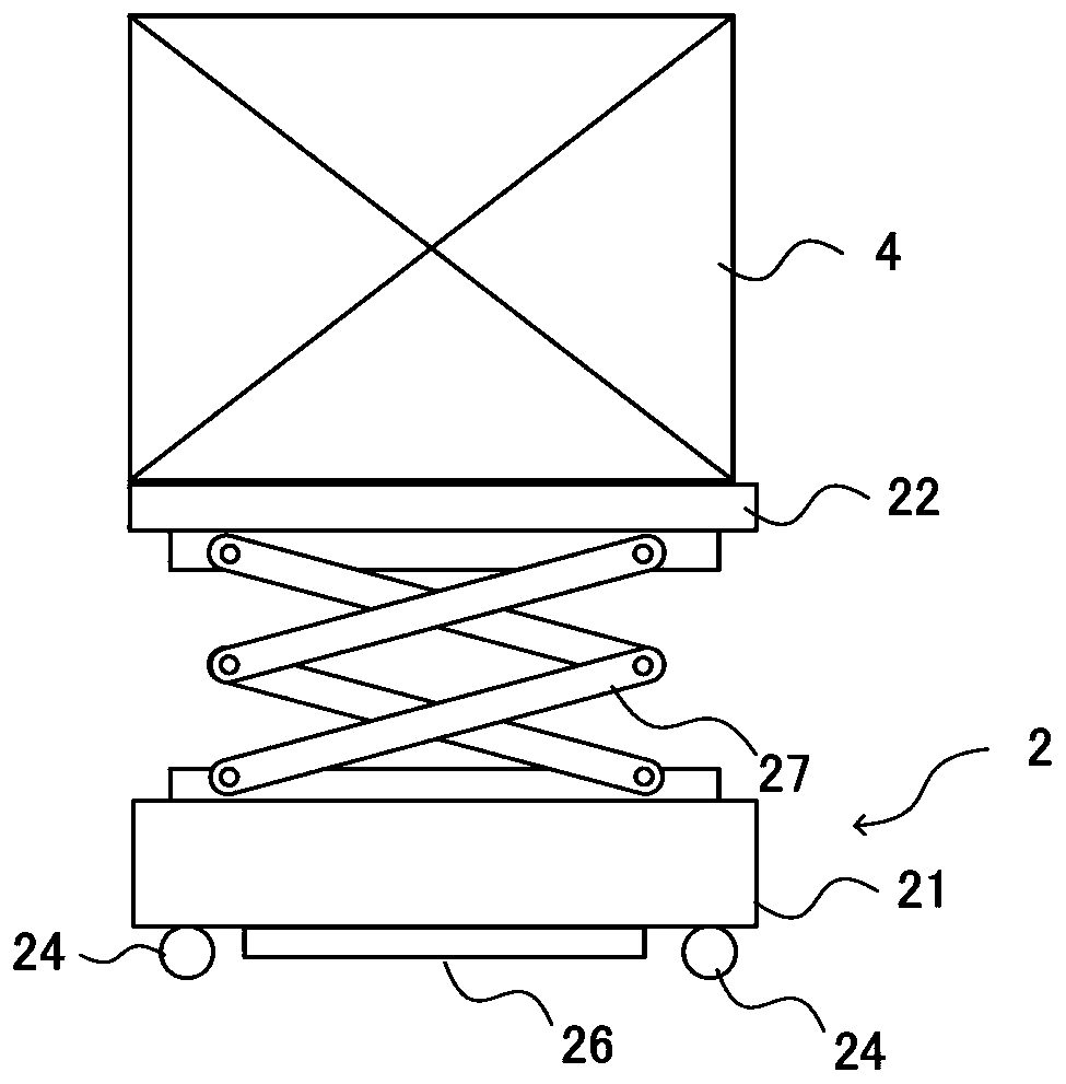
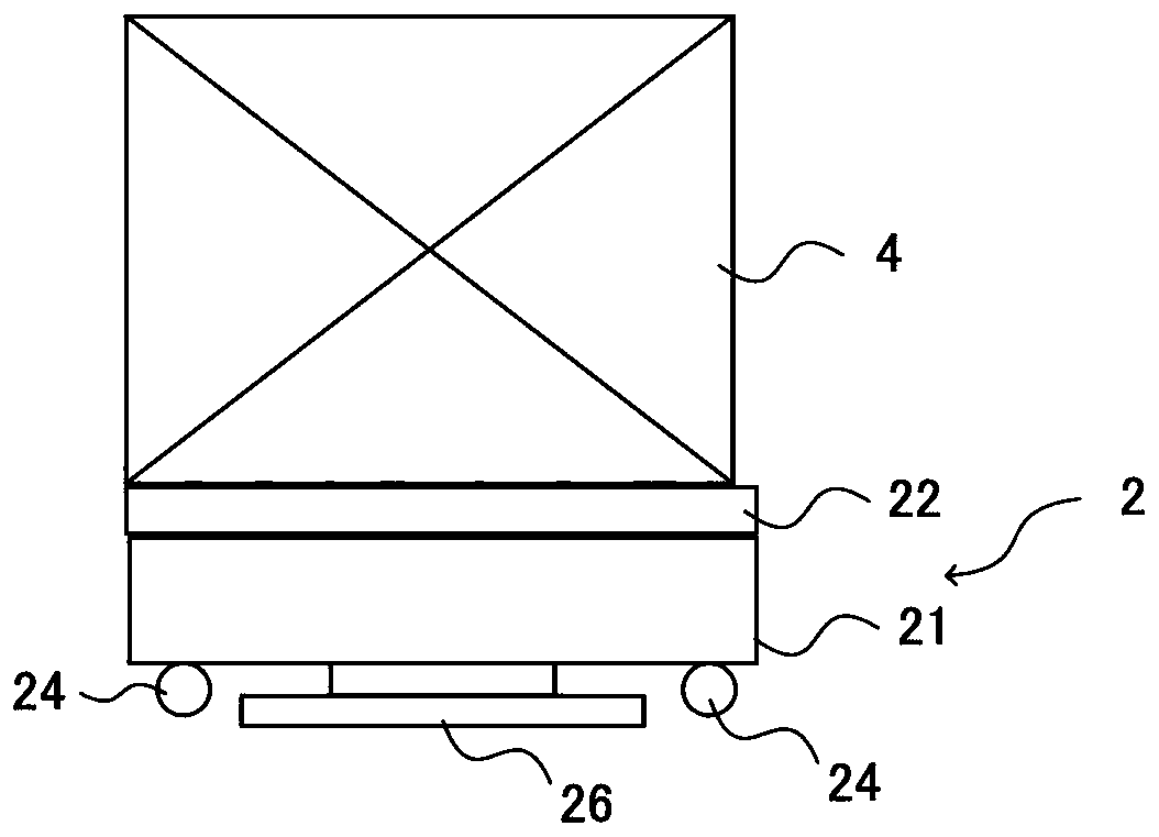
[0054] A first embodiment of the transport device of the present invention will be described in detail with reference to the following drawings. figure 1 It is a perspective view which shows the use state of the conveyance apparatus 1A of this embodiment which consists of a self-propelled vehicle and an operation apparatus. figure 2 and image 3 It is a figure which shows the external appearance structure of the conveyance apparatus of this embodiment. Figure 4 It is a block diagram showing the basic internal configuration of the operating device of this embodiment. Figure 5 It is a bottom view of the conveyance apparatus of this embodiment. Figure 6 It is an instruction manual showing the state of the elevator halls and elevator cars on the floors F1 and F2 using the conveying device of the present embodiment.
[0055] For example figure 1 As shown, the conveying device 1A of this embodiment is a device that ca...
no. 2 approach
[0080] (The overall structure of the transport device)
[0081] Next, the second embodiment of the transport device of the present invention will be described in detail. The transportation device 1A of the above-mentioned first embodiment is constituted only by the self-propelled trolley 2 and the operating device 52, but the transportation device 1B of the present embodiment is characterized in that, for example, the base unit 3 is arranged outside the elevator car EL. Figure 7 It is a perspective view which shows the usage state of the conveyance apparatus 1B of this embodiment. Figure 8 ~ Figure 13 It is a perspective view showing the external appearance structure of the conveyance apparatus 1B of this embodiment, Figure 14 It is a bottom view showing the state in which the self-propelled trolley and the base unit are connected. Figure 15 It is a block diagram showing the internal structure of the operation device of the conveyance device 1B of this embodiment. Figu...
change example 1
[0101] In addition, the embodiment described above is an example of the present invention. The present invention is not limited to the above-described embodiments, and various changes can be made in accordance with design, etc., including applications, without departing from the technical concept of the present invention.
[0102] For example, if Figure 18 As shown, when a plurality of loads are loaded and unloaded on multiple floors by the elevator car EL, the base unit 3 can be arranged only on the floor where the loads are loaded (floor F1 in the illustrated example). Thus, when loading goods on the floor F1, the worker L1 uses the base device to carry the goods into the elevator car EL, and on each target floor, for example, the floor F2, the worker L2 only uses the operating device 52 to carry out the unloading process.
[0103] Accordingly, on the floor where loading operations are concentrated (floor F1 here), the base device 3 can be used to efficiently carry in good...
PUM
 Abstract
Description
Claims
Application Information
 - R&D Engineer
- R&D Manager
- IP Professional
- Industry Leading Data Capabilities
- Powerful AI technology
- Patent DNA Extraction
Browse by: Latest US Patents, China's latest patents, Technical Efficacy Thesaurus, Application Domain, Technology Topic, Popular Technical Reports.
© 2024 PatSnap. All rights reserved.Legal|Privacy policy|Modern Slavery Act Transparency Statement|Sitemap|About US| Contact US: help@patsnap.com