Repeated locking and releasing mechanism of on-orbit load module
A technique for repeatedly locking and releasing mechanisms, which is applied to aerospace equipment, tools, transportation and packaging, etc. It can solve problems such as high design and production costs, no positioning of locking bars, and easy-to-break module contact parts, etc., to improve the use of The effect of longevity
- Summary
- Abstract
- Description
- Claims
- Application Information
AI Technical Summary
Problems solved by technology
Method used
Image

Examples
Embodiment 1
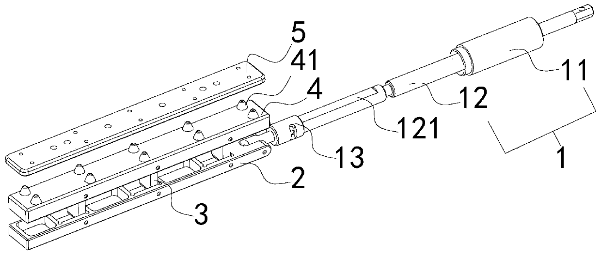
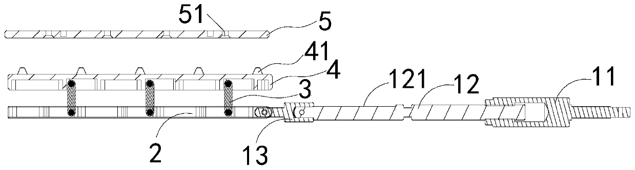
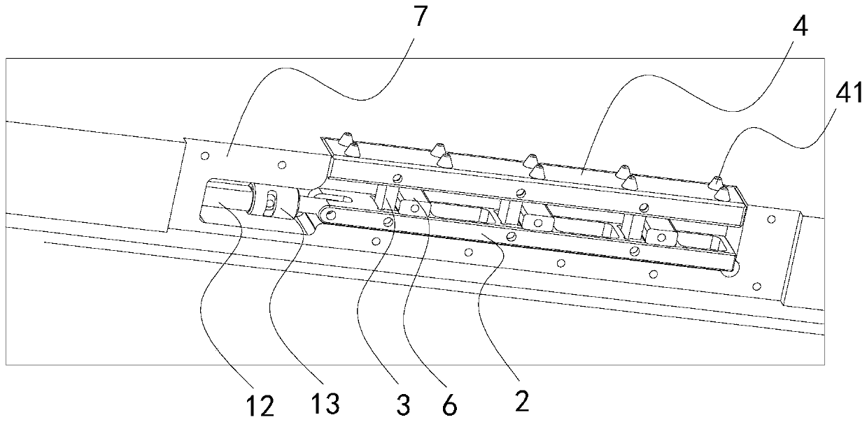
[0044] like Figure 1-4 As shown, a repetitive locking and releasing mechanism for an on-rail load module includes a lead screw linkage mechanism 1, a transverse push block 2, a connecting rod 3, a longitudinal push block 4 and a locking mechanism 5, and the transverse push block 2 is connected with the lead screw. The translation end of the moving mechanism 1 is connected, and the vertical push block 4 and the horizontal push block 2 are arranged in parallel; the two ends of the connecting rod 3 are respectively connected with the vertical push block 4 and the horizontal push block 2; One side is provided with a locking protrusion 41;
[0045] The locking mechanism 5 is provided with a locking groove 51 corresponding to the locking protrusion 41, and the locking protrusion 41 is matched with the locking groove 51;
[0046] Among them, the horizontal push block 2 is translated under the drive of the translation end of the lead screw linkage mechanism 1, and the vertical push ...
Embodiment 2
[0050] like Figure 1-4 As shown, a repetitive locking and releasing mechanism for an on-rail load module includes a lead screw linkage mechanism 1, a transverse push block 2, a connecting rod 3, a longitudinal push block 4 and a locking mechanism 5, and the transverse push block 2 is connected with the lead screw. The translation end of the moving mechanism 1 is connected, and the vertical push block 4 and the horizontal push block 2 are arranged in parallel; the two ends of the connecting rod 3 are respectively connected with the vertical push block 4 and the horizontal push block 2; One side is provided with a locking protrusion 41;
[0051] The locking mechanism 5 is provided with a locking groove 51 corresponding to the locking protrusion 41, and the locking protrusion 41 is matched with the locking groove 51;
[0052] Among them, the horizontal push block 2 is translated under the drive of the translation end of the lead screw linkage mechanism 1, and the vertical push ...
PUM
 Abstract
Description
Claims
Application Information
 - R&D
- Intellectual Property
- Life Sciences
- Materials
- Tech Scout
- Unparalleled Data Quality
- Higher Quality Content
- 60% Fewer Hallucinations
Browse by: Latest US Patents, China's latest patents, Technical Efficacy Thesaurus, Application Domain, Technology Topic, Popular Technical Reports.
© 2025 PatSnap. All rights reserved.Legal|Privacy policy|Modern Slavery Act Transparency Statement|Sitemap|About US| Contact US: help@patsnap.com