Cargo grabbing system for unmanned aerial vehicle
A technology for unmanned aerial vehicles and cargo, which is applied to conveyor objects, unmanned aircraft, rotorcraft, etc., can solve the problems of poor reliability of the device, high manufacturing cost and high energy consumption, and achieve the effect of ingenious mechanism
- Summary
- Abstract
- Description
- Claims
- Application Information
AI Technical Summary
Problems solved by technology
Method used
Image
Examples
specific Embodiment approach 1
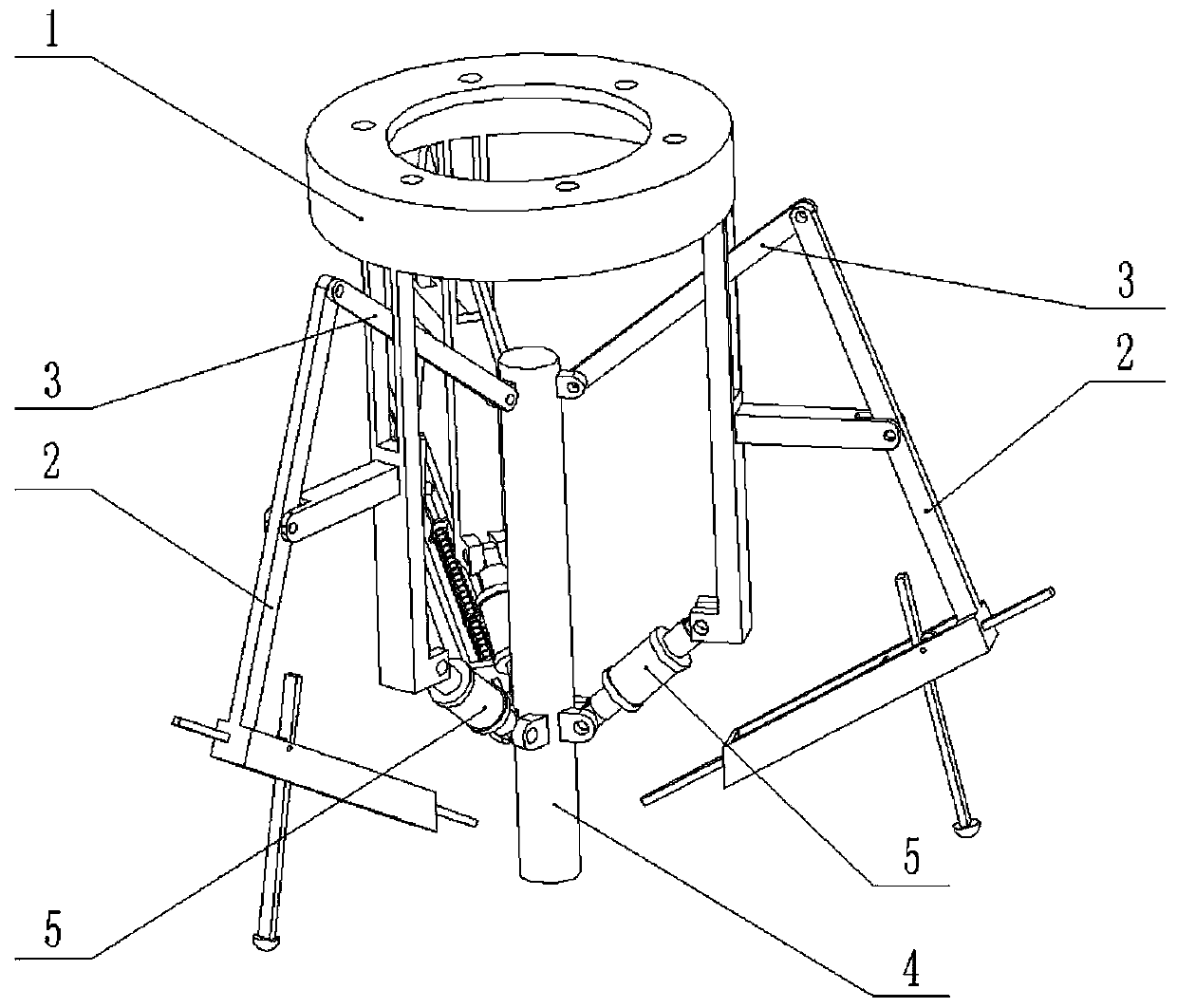
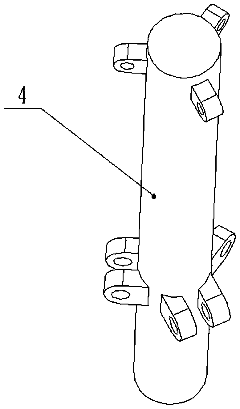
[0024] Combine below Figure 1-9 Description of this embodiment, a cargo grabbing system for unmanned aerial vehicles, including a frame 1, a grabbing device 2, a grabbing link 3, a cargo jack 4 and an elastic support rod 5, the grabbing device 2 is provided with Multiple, the middle ends of multiple grabbing devices 2 are all hingedly connected on the frame 1, one end of the grabbing link 3 is hingedly connected to the upper end of the grabbing device 2, and the other end of the grabbing link 3 is hingedly connected On the upper end of the cargo top column 4, one end of the elastic support rod 5 is hingedly connected to the lower end of the frame 1, and the other end of the elastic support rod 5 is hingedly connected to the cargo top column 4, and a plurality of grasping links 3 The inner sides of the two sides are all inclined downward; in the initial state, the elastic support rod 5 is elastically elongated, and under the support of the elastic support rod 5, the cargo top ...
specific Embodiment approach 2
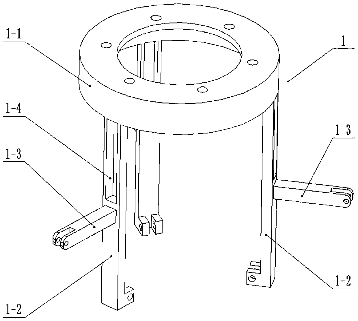
[0027] Combine below Figure 1-9 Describe this embodiment, this embodiment will further explain Embodiment 1, the frame 1 includes a flange sleeve 1-1, a bracket arm 1-2 and a connecting rod strut 1-3, and the flange sleeve 1-1 The lower end of the support arm 1-2 is uniformly fixedly connected to a plurality of support arms 1-2, and the middle ends of the plurality of support arms 1-2 are respectively fixedly connected to the connecting rod strut 1-3, and the upper end of the support arm 1-2 is provided with a connecting rod chute 1 -4, the middle end of the grasping device 2 is hingedly connected to the connecting rod 1-3, the grasping connecting rod 3 is clearance-fitted in the connecting rod chute 1-4, and a plurality of support arms 1-2 Each of the lower ends is hingedly connected with an elastic support rod 5.
specific Embodiment approach 3
[0029] Combine below Figure 1-9 Describe this embodiment, this embodiment will further explain the first embodiment, the elastic support rod 5 includes two insertion rods 5-1, a spring sleeve 5-2, two spring sleeve end caps 5-3 and a support spring 5- 4. The two inserting rods 5-1 are slidably connected to the two ends of the spring sleeve 5-2, the support spring 5-4 is set in the spring sleeve 5-2, and the support spring 5-4 is located on the two inserting rods 5-1, two spring sleeve end caps 5-3 are respectively connected to the two ends of the spring sleeve 5-2 through thread fit, and the two insertion rods 5-1 are respectively slidingly connected to the two spring sleeve end caps 5 In the through hole on the -3; two inserting rods 5-1 compress the support spring 5-4 inwardly, can realize the length change of the elastic support rod 5; Insert rod 5-1 carries out axial limit.
PUM
 Abstract
Description
Claims
Application Information
 - R&D
- Intellectual Property
- Life Sciences
- Materials
- Tech Scout
- Unparalleled Data Quality
- Higher Quality Content
- 60% Fewer Hallucinations
Browse by: Latest US Patents, China's latest patents, Technical Efficacy Thesaurus, Application Domain, Technology Topic, Popular Technical Reports.
© 2025 PatSnap. All rights reserved.Legal|Privacy policy|Modern Slavery Act Transparency Statement|Sitemap|About US| Contact US: help@patsnap.com


