Crane anti-swing device and working method thereof

An anti-sway and crane technology, applied in the directions of cranes, transportation and packaging, load hanging components, etc., can solve the problem that the crane anti-sway device cannot be placed stably, cannot reduce the vibration sense of the crane anti-sway device, and reduce the safety of the crane anti-sway device, etc. question

Inactive Publication Date: 2020-04-24
安徽江河智能装备集团有限公司
View PDF7 Cites 3 Cited by
  • Summary
  • Abstract
  • Description
  • Claims
  • Application Information

AI Technical Summary

Problems solved by technology

[0004] The existing crane anti-sway device has certain disadvantages during use. The traditional crane anti-sway device does not have an inclination angle adjustment structure, so that when the traditional crane anti-sway device is placed on a sloping ground, it will be affected by the inclination angle of the ground. The anti-sway device itself is tilted, which makes it impossible for the crane anti-sway device to keep the crane in a balanced state, which reduces its scope of application; at the same time, the traditional crane anti-sway device does not have a tilt auxiliary fixing structure, so that the traditional crane anti-sway device cannot be placed stably The use on inclined ground reduces the safety of the crane anti-sway device when used on inclined ground; secondly, the traditional crane anti-sway device does not have multiple support structures, which reduces the stability of the crane anti-sway device when it is used, and cannot reduce the external impact. The shock generated by the anti-sway device of the crane will bring certain adverse effects to the user

Method used


Image

  • Crane anti-swing device and working method thereof
  • Crane anti-swing device and working method thereof
  • Crane anti-swing device and working method thereof

Examples


Embodiment Construction

[0033] The technical solutions in the embodiments of the present invention will be clearly and completely described below in conjunction with the embodiments of the present invention. Apparently, the described embodiments are only some of the embodiments of the present invention, not all of them. Based on the embodiments of the present invention, all other embodiments obtained by persons of ordinary skill in the art without creative efforts fall within the protection scope of the present invention.

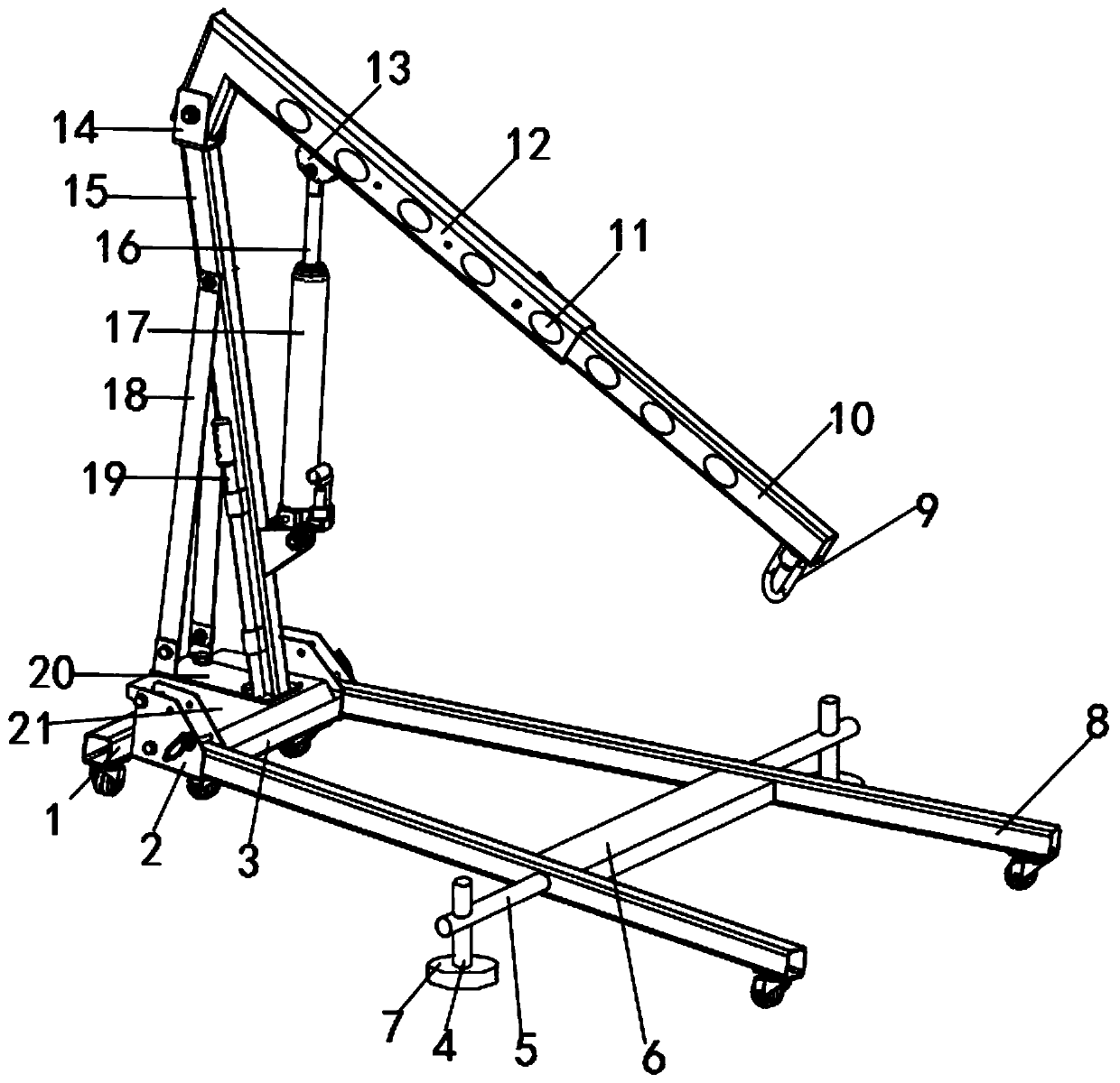
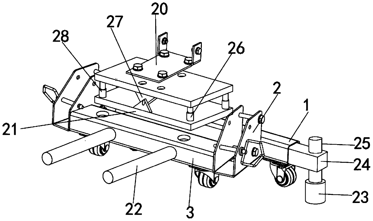
[0034] like Figure 1-6 As shown, an anti-swing device for a crane includes a supporting foot frame 8, a fixed base plate 3, a balance base plate 21, a fixed support arm 15, a telescopic arm 10 and a side-swivel foot rod 4, and the outer surfaces of both sides of the fixed base plate 3 are fixedly installed with The docking base 2, the supporting foot 8 is fixedly installed on the front of the fixed bottom plate 3, the side-swivel foot rod 4 is movably installed on one side of the...


PUM


Abstract

The invention discloses an anti-swing device of a crane. The device comprises a supporting foot stand, a fixed bottom plate, a balance bottom plate, a fixed supporting arm, a telescopic arm and a siderotating foot rod. Butt joint clamping seats are fixedly mounted on the outer surfaces of the two sides of the fixed bottom plate. The supporting foot stand is fixedly mounted at the front part of the fixed bottom plate. The side rotating foot rod is movably installed on one side of the supporting foot stand. The outer surface of the side rotating foot rod is movably sleeved by a side rotating clamping rod. Inclined supporting feet are movably installed at the bottom of the side rotating foot rod. Spherical clamping grooves are formed in the middles of the inner sides of the inclined supporting feet. A ball clamping pin is fixedly installed on the outer surface of the lower end of the side rotating foot rod. The upper portion, fixedly close to the ball clamping pin, of the outer surface of the side rotating foot rod is movably sleeved by a fixing clamping sleeve. According to the crane anti-swing device, the crane anti-swing device is provided with an inclination angle adjusting structure, so that the stability of the crane anti-swing device is improved; meanwhile, the crane anti-swing device is provided with an inclination auxiliary fixing structure, so that the fixing operationis firmer, and the anti-swing effect of the crane anti-swing device is improved.

Description

technical field [0001] The invention belongs to the technical field of crane equipment, in particular relates to a crane anti-sway device, and more specifically relates to a crane anti-sway device and a working method thereof. Background technique [0002] The crane anti-sway device is an anti-sway device that plays an auxiliary role in fixing the crane during the hoisting process of the crane. The use of the crane anti-sway device can make the use of the crane more stable and prevent the crane from being lifted during the hoisting process. There is a shaking phenomenon, which effectively improves the stability of the crane when it is in use. [0003] The reference document CN103395692B discloses an anti-swing device for clamping modules, which includes a device body and a clamping module, the device body is hinged to one end of the clamping module, and a hydraulic damping system, which includes a hydraulic Cylinder and speed regulating valve, the cylinder body of the hydra...

Claims


Application Information

Patent Timeline
Patent Type & Authority Applications(China)
IPC IPC(8): B66C13/06B66C23/69B66C23/78
CPCB66C13/066B66C23/701B66C23/78
Inventor 梁大伟
Owner 安徽江河智能装备集团有限公司
Why Eureka
Try Eureka