
Energy-saving anti-freezing power distribution cabinet

An energy-saving technology for power distribution cabinets, which is applied in the field of energy-saving antifreeze power distribution cabinets. It can solve the problems of high airtightness of the interlayer structure of the box body, cracking of the cabinet body, danger, etc., and solve the problems of abnormal use and constant temperature. , good sealing effect

Inactive Publication Date: 2020-04-24
武汉心动驿站供应链管理有限公司
View PDF12 Cites 3 Cited by
  • Summary
  • Abstract
  • Description
  • Claims
  • Application Information

AI Technical Summary

Problems solved by technology

This kind of power distribution cabinet can be used normally in a normal temperature environment, but when used outdoors in severe cold seasons or in northern regions, affected by rain and snow, the outside and around the cabinet door are very easy to freeze, resulting in the door being unable to open, and even the cabinet body freezing. Cracks, damage to internal electrical components and other serious consequences
[0003] In recent years, there has also been an antifreeze technology that makes the box into a sandwich, installs a thermal fluid inside and heats the heating element immersed in the thermal fluid to increase the temperature of the box, but due to its large energy consumption, the operating cost is high , and the tightness requirements for the sandwich structure of the box body are relatively high, once leakage occurs, it may cause dangerous consequences

Method used


Image

  • Energy-saving anti-freezing power distribution cabinet
  • Energy-saving anti-freezing power distribution cabinet
  • Energy-saving anti-freezing power distribution cabinet

Examples


Embodiment Construction

[0022] The present invention will be further described below in conjunction with specific embodiments. The exemplary embodiments and descriptions of the present invention are used to explain the present invention, but not as a limitation to the present invention.

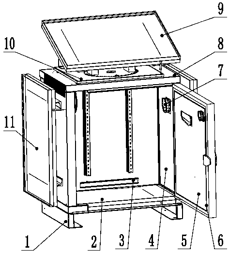
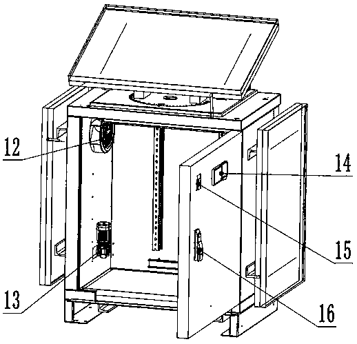
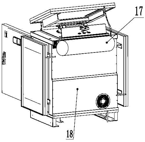
[0023] Example: such as figure 1 , 2 , 3, 4 shows an energy-saving antifreeze power distribution cabinet, including base 1, box bottom plate 2, slide rail 3, box side plate 4, door 5, sealing strip 6, temperature controller 7, box top plate 8. Top solar collector 9, sun tracking device 10, side solar collector 11, heat circulation fan 12, circulation pump 13, embedded control panel 14, temperature control switch 15, door lock 16, water tank 17, box Body back plate 18, heat circulation pipeline 19, insulation cotton 20, base 1 is a sheet metal frame structure, fixedly installed on the ground, box bottom plate 2, box side plate 4, box top plate 8, box back plate 18 Assembled together into an open box, its bottom sur...


PUM


Abstract

The invention discloses an energy-saving anti-freezing power distribution cabinet. The power distribution cabinet comprises a base, a box body, a sliding rail, a box door, a sealing strip, a temperature controller, solar heat collectors, a solar tracking device, a heat circulating fan, a circulating pump, an embedded control panel, a temperature control switch, a door lock, a water tank, a heat circulating pipeline and a heat preservation material. Interlayers are arranged in the box body and the box door, heat circulation pipelines are arranged in the interlayers, internal circulation mediumwater of the heat circulation pipelines comes from the water tank, and after being heated by the solar heat collectors arranged at the top and on the side faces, the internal circulation medium watercirculates in the whole pipelines under the driving of the circulation pump to heat the whole box body. The circulating fan and the temperature controller are arranged in the box door and connected with the control switch and the control panel on the box door, and the sealing strip is arranged on the periphery of the box door. When external weather is cold and the temperature is too low, the temperature controller can control a circulating device to carry out heat circulation according to the surrounding environment and the internal temperature, it is guaranteed that the box body and the box door cannot be frozen, and electrical elements in the box cannot be damaged.

Description

technical field [0001] The invention relates to a power distribution cabinet of a power system, more specifically, it relates to an energy-saving antifreeze power distribution cabinet suitable for use in severe cold weather. Background technique [0002] At present, the power distribution cabinets on the market generally include a box body and a box door, and most of them are single-layer structures. This kind of power distribution cabinet can be used normally in a normal temperature environment, but when used outdoors in severe cold seasons or in northern regions, affected by rain and snow, the outside and around the cabinet door are very easy to freeze, resulting in the door being unable to open, and even the cabinet body freezing. Cracks, damage to internal electrical components and other serious consequences. [0003] In recent years, there has also been an antifreeze technology that makes the box into a sandwich, installs a thermal fluid inside and heats the heating el...

Claims


Application Information

Patent Timeline
Patent Type & Authority Applications(China)
IPC IPC(8): H02B1/30H02B1/38H02B1/56F24S50/20F24S30/452
CPCF24S30/452F24S50/20H02B1/301H02B1/303H02B1/306H02B1/38H02B1/565Y02E10/47
Inventor 王凯盛
Owner 武汉心动驿站供应链管理有限公司
Learn More