Supercharge Your Innovation With Domain-Expert AI Agents!

A multi-purpose circuit device and multi-purpose circuit control method

A circuit and equipment technology, applied in the field of multi-purpose circuit equipment and multi-purpose circuit control, can solve the problems of application scene limitation, frame rate loss, discarding, etc., and achieve the effects of cost reduction, high performance and stable frame rate

Active Publication Date: 2021-08-20
ANYKA (GUANGZHOU) MICROELECTRONICS TECH CO LTD
View PDF9 Cites 0 Cited by
  • Summary
  • Abstract
  • Description
  • Claims
  • Application Information

AI Technical Summary

Problems solved by technology

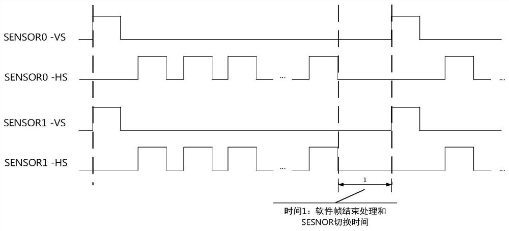
Because the timing relationship between image sensors is completely asynchronous, the number of effective frames that each image sensor can be collected and processed by the ISP is unstable within a period of time. At the same time, the ISP will discard incomplete frames, and the performance is not fully utilized. loss
Although time-division multiplexing ISP can effectively reduce costs, if the stability of the frame rate cannot be guaranteed and frame synchronization is not performed between image sensors, the application scenarios will be greatly limited, and the performance of the ISP cannot be fully utilized.
Taking the binocular application as an example, if the input of each image sensor is 1080P@30fps, the ISP processing capacity is 1080P@30fps, because the two image sensors are asynchronous, in the worst case, the ISP needs to switch to another image sensor every time. Only 2 frames can receive 1 frame, so the processing capability of the ISP can only display about 1080P@7.5fps

Method used


Image

  • A multi-purpose circuit device and multi-purpose circuit control method
  • A multi-purpose circuit device and multi-purpose circuit control method
  • A multi-purpose circuit device and multi-purpose circuit control method

Examples


Embodiment Construction

[0038] The following will clearly and completely describe the technical solutions in the embodiments of the present invention with reference to the accompanying drawings in the embodiments of the present invention. Obviously, the described embodiments are only some, not all, embodiments of the present invention. Based on the embodiments of the present invention, all other embodiments obtained by persons of ordinary skill in the art without creative efforts fall within the protection scope of the present invention.

[0039] Figure 6 It is a sequential circuit diagram of a conventional image sensor in the prior art, VSYNC is a frame synchronization signal, (1) is the time of one frame image; HREF is a line synchronization signal, marking the time of one row of valid data; D[9:0] for pixel data. When the image sensor works in the main mode, it will output image data according to a fixed timing. For multi-eye applications, when multiple image sensors work in the main mode, they...


PUM


Abstract

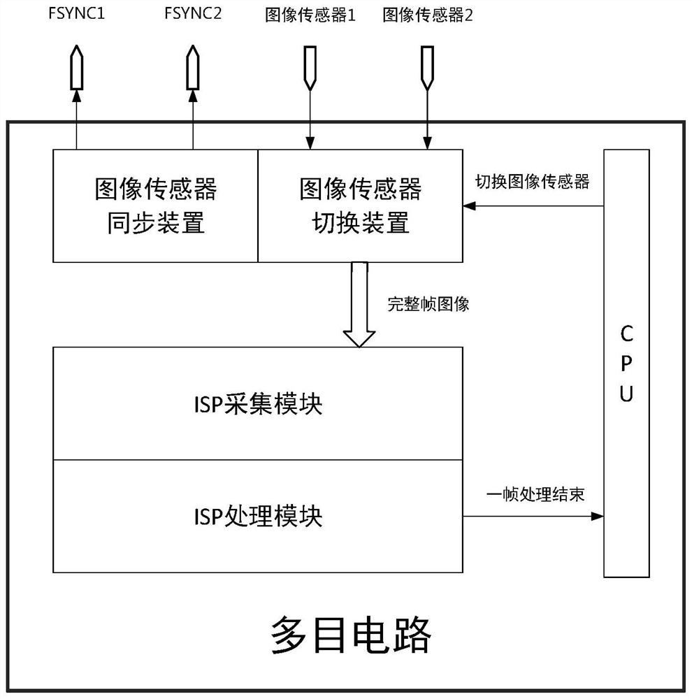
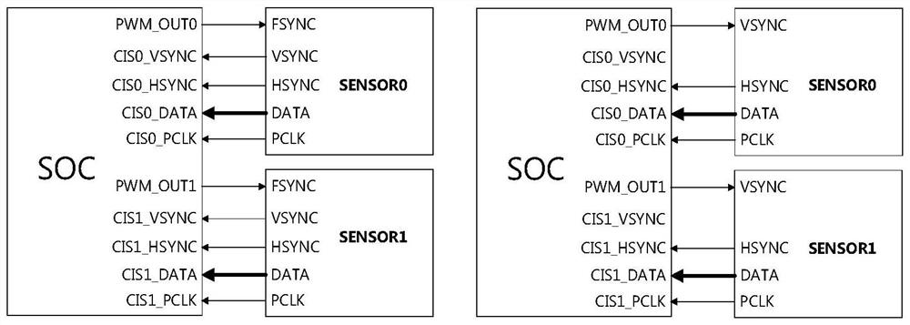
The invention discloses a multi-purpose circuit device, comprising: a CPU, an image sensor synchronizing device, an image sensor switching device and an ISP device; the image sensor synchronizing device is used to generate a synchronous trigger signal and send the synchronous trigger signal; To receive the switching signal, switch the image sensor according to the switching signal, and filter the complete frame; the ISP device includes an ISP acquisition module and an ISP processing module; the ISP acquisition module is used to receive the complete frame image and perform preliminary image processing on the frame image; The ISP processing module is used to perform image algorithm processing on the preliminarily processed frame image, and generate an end interrupt signal after the processing is completed; the present invention sends a synchronous trigger signal to the image sensor by setting the ISP device in conjunction with the synchronization device, so that the external image sensor performs frame processing. Synchronization, so as to keep the frame rate received and processed by the ISP device stable, so that the ISP device can exert the maximum performance and greatly reduce the cost of the SOC chip.

Description

technical field [0001] The invention relates to the field of multi-purpose circuits, in particular to a multi-purpose circuit device and a multi-purpose circuit control method. Background technique [0002] ISP (Image Sensor Processor) can compensate for the hardware defects of the image sensor, or optimize the image display effect to obtain high-definition and high-quality images. The ISP module is usually used as one of the components of a SOC (System On Chip, System on Chip) chip, and is used in scenarios such as mobile phone chips, security chips, or vehicle cameras. More and more scenes will use multiple image sensors, such as VR panoramic shooting, 360 0 Reversing camera system and dual-camera mobile phone, etc. For such multi-purpose applications, the problem to be solved in this patent is to use a single ISP module for time-division multiplexing, to process only one image at a certain time, and to ensure the frame rate of the collected and processed images to be st...

Claims


Application Information

Patent Timeline
Patent Type & Authority Patents(China)
IPC IPC(8): H04N5/232H04N5/357
CPCH04N23/60H04N25/60
Inventor 兰田田胡胜发
Owner ANYKA (GUANGZHOU) MICROELECTRONICS TECH CO LTD
Features
  • R&D
  • Intellectual Property
  • Life Sciences
  • Materials
  • Tech Scout
  • Unparalleled Data Quality
  • Higher Quality Content
  • 60% Fewer Hallucinations
Learn More