Coiled material conveying device and adjusting method of conveying device

A coil conveying device and coil technology, which are applied in the direction of coiling strips, transportation and packaging, thin material handling, etc., can solve problems such as increasing power loss, damaging machines, and increasing production costs.

Active Publication Date: 2020-04-28
佛山市三水凤铝铝业有限公司 +1
View PDF6 Cites 6 Cited by
  • Summary
  • Abstract
  • Description
  • Claims
  • Application Information

AI Technical Summary

Problems solved by technology

[0003] However, the solution of the existing coil conveyor to the synchronization problem with the production line is not perfect enough. The braking of the existing coil conveying device is mainly performed by the friction between the turntable and the side disk or with the rotating shaft, such as The roll of the coil conveyor pulls the coil through the tractor to drive the conveyor to rotate and feed the material. When the tractor stops running, the coil conveyor loses power and will gradually slow down until it stops due to friction, increasing the friction The braking time can be reduced, but the two machines cannot achieve good synchronization, so some materials will continue to be conveyed, and the materials between the two devices will be squeezed and twisted, which will affect the quality of the materials or even destroy the materials. This kind of friction will also decrease after a long time of use, thereby reducing the efficiency of braking, making the braking effect less obvious, and this friction is useless in normal use, which will increase power loss and increase production costs or even damage machine
[0004] Therefore, the synchronization problem of the existing coil conveyor has not been better resolved

Method used


Image

  • Coiled material conveying device and adjusting method of conveying device
  • Coiled material conveying device and adjusting method of conveying device
  • Coiled material conveying device and adjusting method of conveying device

Examples


Embodiment 1

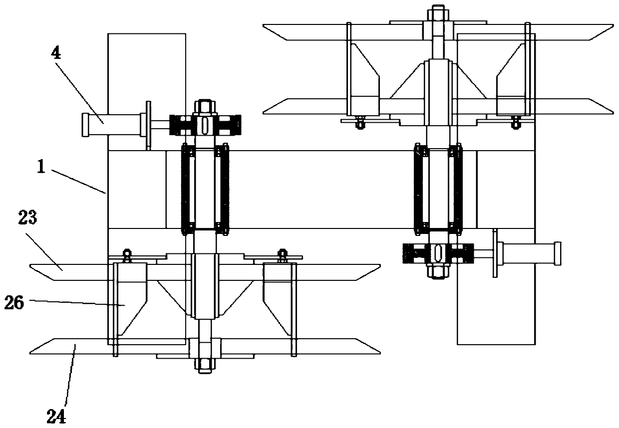
[0046] like Figure 1 to Figure 11 As shown, a coil conveying device includes a frame 1, and also includes:

[0047] The coiled material fixing structure 2 is used to install and fix the coiled material, and rotate synchronously with the coiled material. The coiled material fixing structure 2 can adjust the telescopic position of the tensioning assembly 26 by rotating the first turntable 23 to meet the needs of different coils. The inner ring size of the material needs to be different;

[0048] The brake locking structure 4 is used to quickly brake the coiled material fixing structure 2;

[0049] The stop structure 3 is used to fix the locking disc 25 of the coil fixing structure 2 and assist the adjustment of the tensioning assembly 26 at the same time.

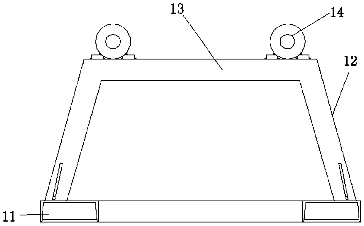
[0050] Described frame 1 comprises base plate 11, support bar 12, cross frame 13, bearing 16 seat 14, shaft cover 15 and bearing 16, and described support bar 12 is fixedly installed on the base plate 11, and described cro...

Embodiment 2

[0062] Embodiment 2, this embodiment is a further description of the coil conveying device of the embodiment, specifically:

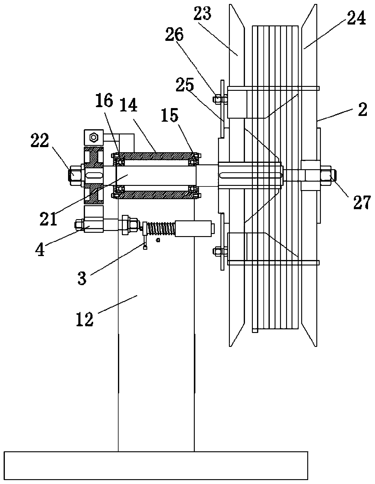
[0063] A coil conveying device, comprising a frame 1, a coil fixing structure 2, a brake locking structure 4, and a stop structure 3. The frame 1 includes a bottom plate 11, a support rod 12, a horizontal frame 13, a bearing 16 seat 14, A shaft cover 15 and a bearing 16, the support rod 12 is fixedly installed on the bottom plate 11, the cross frame 13 is mounted on the support rod 12, the bearing 16 seat 14 is mounted on the cross frame 13, and the shaft cover 15 uses Fasteners are installed on both sides of the bearing 16 seat 14, and the bearing 16 is arranged on the inner side of the bearing 16 seat 14;

[0064] The coil fixing structure 2 includes a main shaft 21, a left limiter 22, a first turntable 23, a second turntable 24, a locking disc 25, a tensioning assembly 26 and a right limiter 27. The left limiter 22 Installed on the left end of the m...


PUM


Abstract

The invention provides a coiled material conveying device and an adjusting method of the conveying device, and belongs to the field of coiled material production and processing. The coiled material conveying device includes a coiled material fixing structure, a brake locking structure and a stop structure. The coiled material fixing structure is mainly used for installing and fixing coiled materials, and synchronously rotates with the coiled materials. The coiled material fixing structure can adjust the expansion and contraction position of a tensioning component by rotating a first rotary table to meet the needs of different inner ring sizes of the different coiled materials. The brake locking structure is used for quickly braking and stopping the coiled material fixing structure. The stop structure is used for fixing a locking disc of the coiled material fixing structure and assisting the adjustment of the tensioning component at the same time.

Description

technical field [0001] The invention relates to the field of coil production and processing, in particular to a coil conveying device and a method for adjusting the conveying device. Background technique [0002] Existing coils (such as aluminum coils, steel coils, etc.) need to be sorted, fixed and transported by a coil conveying device when entering other production processes, and then the coils can be transported to the next one in a smooth and orderly manner. Processing is carried out in the process, so the coil conveyor is used as the first device of the process. Without the coil conveyor, it is difficult to start each process. [0003] However, the solution of the existing coil conveyor to the synchronization problem with the production line is not perfect enough. The braking of the existing coil conveying device is mainly performed by the friction between the turntable and the side disk or with the rotating shaft, such as The roll of the coil conveyor pulls the coil ...

Claims


Application Information

Patent Timeline
Patent Type & Authority Applications(China)
IPC IPC(8): B65H75/30B65H75/14B65H23/182
CPCB65H23/1825B65H75/148B65H75/30B65H2515/31
Inventor 林明忠郑裕荣
Owner 佛山市三水凤铝铝业有限公司
Why Eureka
Try Eureka