Vacuum cut-off valve

A shut-off valve and vacuum technology, which is applied in the field of shut-off valves, can solve the problems that the vacuum shut-off valve is prone to failure and affects the passage of fluid semi-solid fluids, etc., so as to improve contact reliability and stability, patency is not affected, and the force is not affected. uniform effect

Pending Publication Date: 2020-04-28
CHENGDU QIANJI ENTERPRISE MANAGEMENT CONSULTING CO LTD
View PDF0 Cites 1 Cited by
  • Summary
  • Abstract
  • Description
  • Claims
  • Application Information

AI Technical Summary

Problems solved by technology

[0005] In order to overcome the deficiencies of the prior art, the present invention provides a vacuum shut-off valve, which solves the problem that the existing vacuum shut-off valve easily affects the passage of fluids, especially semi-solid fluids, and the vacuum shut-off valve is prone to failure

Method used


Image

  • Vacuum cut-off valve
  • Vacuum cut-off valve
  • Vacuum cut-off valve

Examples


Embodiment 1

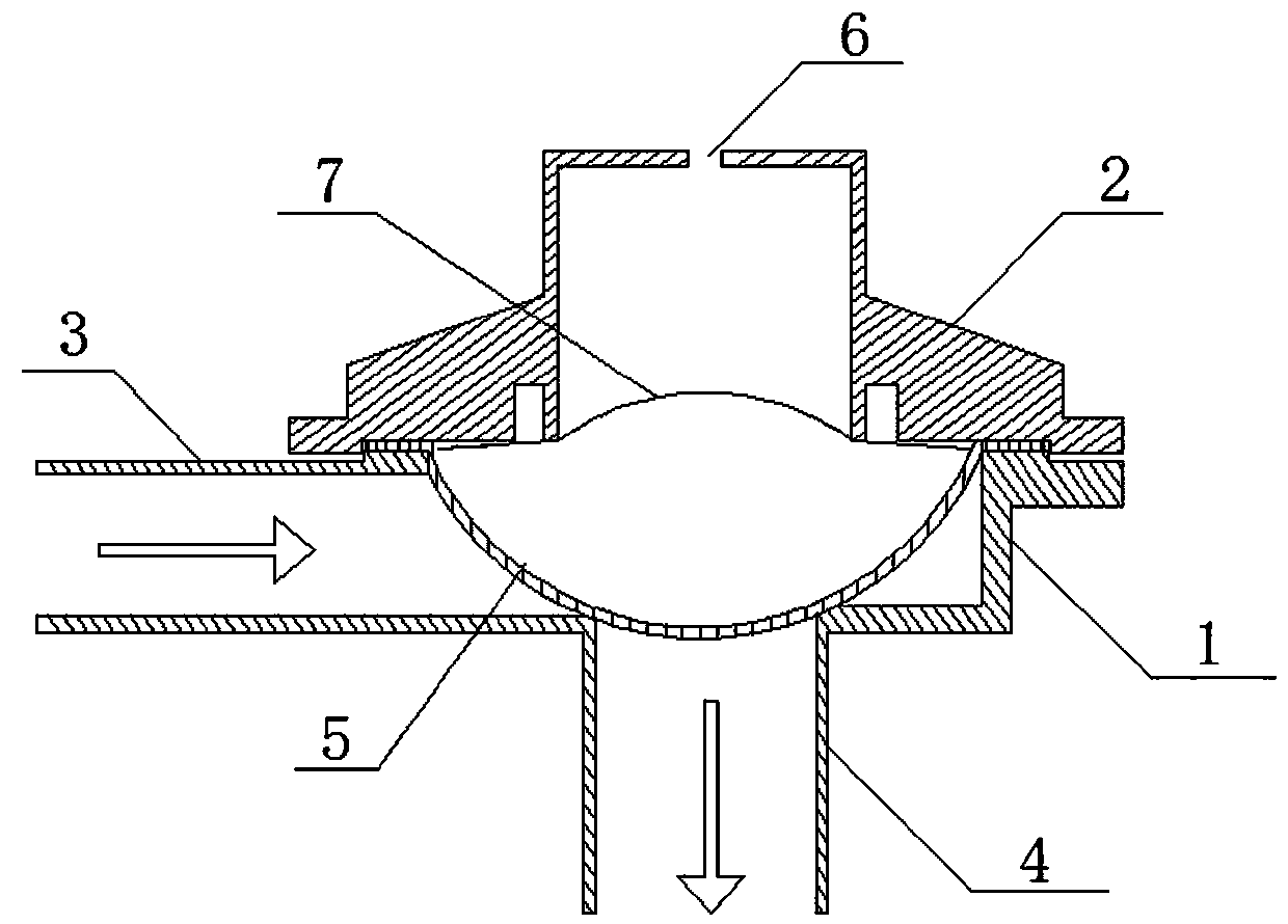
[0031] Such as figure 1 As shown, a vacuum cut-off valve shown in a preferred embodiment of the present invention includes a valve body 1 and a valve cover 2 connected to the valve body 1. The valve body 1 is provided with an inflow channel 3 and an outflow channel 4 communicating with each other. In addition, the inflow channel 3 and the outflow channel 4 are smoothly connected, and the opening of the outflow channel 4 is provided with a deformable partition 5, and the upper space formed by the partition 5 and the valve cover 2 passes through the vacuum negative pressure provided on the top of the valve cover 2. The inlet 6 communicates with the first vacuum source, the first vacuum source is used to control the opening and closing of the partition 5 to the outflow channel 4, the outflow channel 4 communicates with the second vacuum source, and the first vacuum source and the second vacuum source are the same Vacuum source or a different vacuum source.

[0032] The fluid cha...


PUM


Abstract

The invention discloses a vacuum cut-off valve. The vacuum cut-off valve comprises a valve body and a valve cover connected to the valve body; the valve body is provided with an inflow channel and anoutflow channel communicating with each other; the inflow channel is smoothly connected with the outflow channel; a channel opening of the outflow channel is provided with a deformable partition; an upper space formed by the partition and the valve cover communicates with a first vacuum source through a vacuum negative pressure inlet formed in the top of the valve cover; the first vacuum source isused for controlling the opening and closing of the outflow channel by the partition; the outflow channel is in communication with a second vacuum source; and the first vacuum source and the second vacuum source are the same vacuum source or different vacuum sources. The vacuum cut-off valve can improve the passability of a fluid, especially a semi-solid fluid, the airtightness of the vacuum cut-off valve is ensured, and the service life of the vacuum cut-off valve is prolonged.

Description

technical field [0001] The invention relates to the field of stop valves, in particular to a vacuum stop valve. Background technique [0002] The design idea of ​​the existing vacuum shut-off valve is to set a base stem and a cup matching the base stem on the fluid flow channel, and realize the fitting and separation of the base stem and the cup by controlling the deformation of the cup, thereby realizing fluid flow. Opening and closing of flow channels. In addition, in order to better realize the fit and separation between the base stem and the cup, some designs increase the deformation response speed of the cup by adding springs, push rods and other structures. The existing vacuum stop valve has the following problems: [0003] (1) Since the base stem is set on the fluid flow channel, the flow of the fluid will inevitably be hindered, especially when the fluid is semi-solid, it will cause the semi-solid fluid to cross the base stem to pass through the stop valve. The st...

Claims


Application Information

Patent Timeline
Patent Type & Authority Applications(China)
IPC IPC(8): F16K7/12F16K51/02F16K27/00
CPCF16K7/123F16K27/00F16K51/02
Inventor 仰国其
Owner CHENGDU QIANJI ENTERPRISE MANAGEMENT CONSULTING CO LTD
Why Eureka
Try Eureka