Magnetic powder detection device for omnibearing detection of steel structure

A magnetic particle detection, all-round technology, applied in the direction of material magnetic variables, etc., can solve the problems of inconvenient use, low magnetization efficiency, and inability to magnetize workpieces of different sizes.

Pending Publication Date: 2020-04-28
LIAONING JIDIAN POLYTECHNIC
View PDF0 Cites 2 Cited by
  • Summary
  • Abstract
  • Description
  • Claims
  • Application Information

AI Technical Summary

Problems solved by technology

[0003] The current steel structure magnetic particle testing device has a complex structure and is inconvenient to use. It cannot magnetize workpieces of diff

Method used


Image

  • Magnetic powder detection device for omnibearing detection of steel structure
  • Magnetic powder detection device for omnibearing detection of steel structure
  • Magnetic powder detection device for omnibearing detection of steel structure

Examples


Embodiment 1

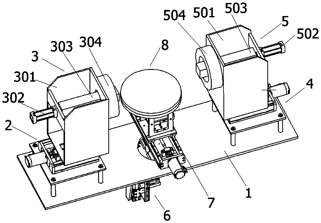
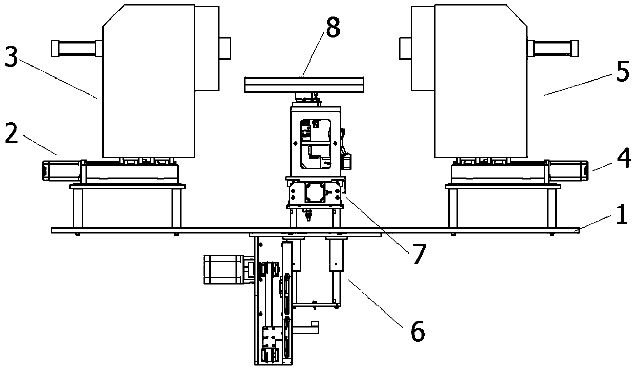
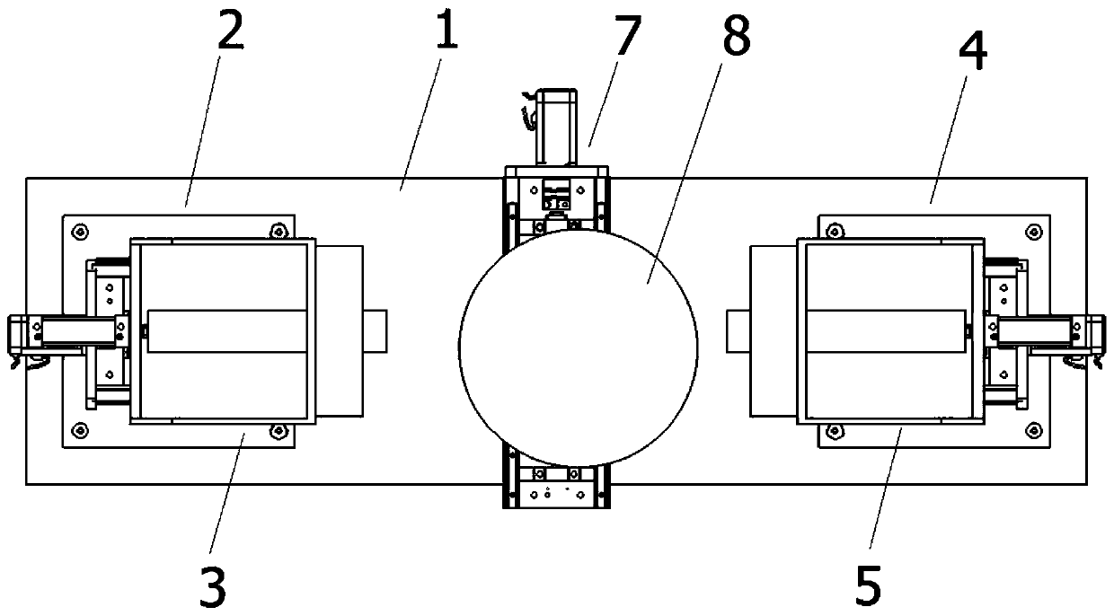
[0036] see Figure 1-8, in an embodiment of the present invention, a magnetic particle inspection device for all-round inspection of steel structures includes a fixed large base plate 1, and a left X-axis driving mechanism 2 is fixed on the left side of the upper end surface of the fixed large base plate 1 by screws. For flaw detection in the X-axis direction of the workpiece, a left magnetic particle flaw detection mechanism 3 is fixed above the left X-axis drive mechanism 2 by screws for flaw detection on the left side of the workpiece. The right X-axis drive mechanism 4 is used for flaw detection in the X-axis direction of the workpiece. The right magnetic particle flaw detection mechanism 5 is fixed above the right X-axis drive mechanism 4 by screws for flaw detection on the right side of the workpiece. The fixed large base plate 1 The middle part of the lower end surface is connected with a Z-axis driving mechanism 6 by screws for flaw detection in the Z-axis direction of...

Embodiment 2

[0046] The rotary platform 8 includes a rotating support plate 801 connected to the upper end surface of the Y-axis moving plate 706 by screws, the upper end surface of the rotating support plate 801 is connected to the upper mounting plate 802 by screws, and the middle part of the upper mounting plate 802 is connected to the bearing seat C803 is connected by screws, and the bearing seat C803 is slidingly connected with the shaft flange 804 to play a role of stable rotation. The lower end of the shaft flange 804 is connected with the reducer 805 through a coupling, and the reducer 805 provides the workpiece The power to rotate in the axial direction, the reducer 805 and the lower end surface of the lower mounting plate 806 are connected by screws, the lower mounting plate 806 is fixed on the inner wall of the rotating support plate 801 by screws, and the upper end surface of the rotating shaft flange 804 is connected to the rotating platform 807 is connected by screws, and the ...


PUM


Abstract

The invention discloses a magnetic powder detection device for omnibearing detection of a steel structure. The device comprises a large fixed bottom plate. A left X-axis driving mechanism is fixed tothe left side of the upper end face of the large fixed bottom plate through screws. A left magnetic powder flaw detection mechanism is fixed above the left X-axis driving mechanism through screws. A right X-axis driving mechanism is fixed to the right side of the upper end face of the large fixed bottom plate through screws. A right magnetic powder flaw detection mechanism is fixed above the rightX-axis driving mechanism through screws. A Z-axis driving mechanism is connected to the middle of the lower end face of the large fixed bottom plate through screws. A Y-axis driving mechanism is fixed above the Z-axis driving mechanism through screws. A rotating platform is fixed above the Y-axis driving mechanism through screws. The device is simple in structure and convenient to use, omnibearing magnetization of workpieces of different sizes can be achieved through the left X-axis driving mechanism, the right X-axis driving mechanism, the Y-axis driving mechanism and the rotating platform,omnibearing cracks can be detected at a time, and the practicability is high.

Description

technical field [0001] The invention relates to the technical field of magnetic particle detection, in particular to a magnetic particle detection device for comprehensive detection of steel structures. Background technique [0002] Magnetic particle flaw detection uses the interaction between the leakage magnetic field at the defect of the workpiece and the magnetic powder. It uses the difference between the magnetic permeability of the surface of the steel product and the near-surface defects (such as cracks, slag inclusions, hairlines, etc.) and the magnetic permeability of the steel. After magnetization, these The magnetic field at the discontinuity of the material will be distorted, forming a part of the magnetic flux leakage, and the leakage magnetic field will be generated on the surface of the workpiece, thereby attracting the magnetic powder to form the magnetic powder accumulation at the defect - the magnetic trace, which shows the position and shape of the defect u...

Claims


Application Information

Patent Timeline
IPC IPC(8): G01N27/84
CPCG01N27/84
Inventor 岳玉国
Owner LIAONING JIDIAN POLYTECHNIC
Why Eureka
Try Eureka