Exposure mechanism of platemaking machine

A technology of plate-making machines and optical drums, applied in optics, instruments, printing equipment, etc., can solve problems such as low production efficiency, complicated exposure process, and large manpower and material resources

Pending Publication Date: 2020-04-28
HANGZHOU CRON MACHINERY & ELECTRONICS CO LTD
View PDF0 Cites 0 Cited by
  • Summary
  • Abstract
  • Description
  • Claims
  • Application Information

AI Technical Summary

Problems solved by technology

However, such an entire exposure process is relatively complicated, requires a l...

Method used


Image

  • Exposure mechanism of platemaking machine
  • Exposure mechanism of platemaking machine
  • Exposure mechanism of platemaking machine

Examples


Embodiment 1

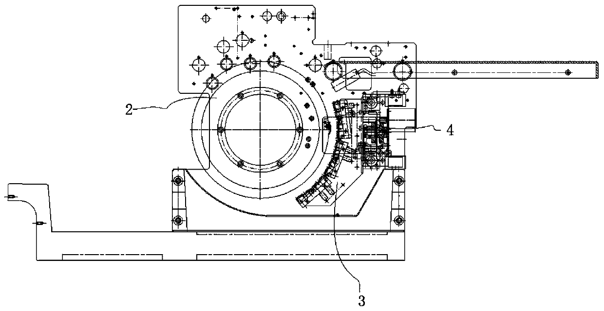
[0017] Embodiment 1: As shown in the figure, an exposure mechanism of a plate-making machine includes a wallboard 1 and a light drum 2. The wallboard 1 is provided with a displaceable actuator assembly 3. Both sides of the wallboard 1 Each end is provided with a transmission assembly 4, the transmission assembly 4 drives the actuator assembly 3 to move, and the actuator assembly 3 is in movable contact with the optical drum 2.

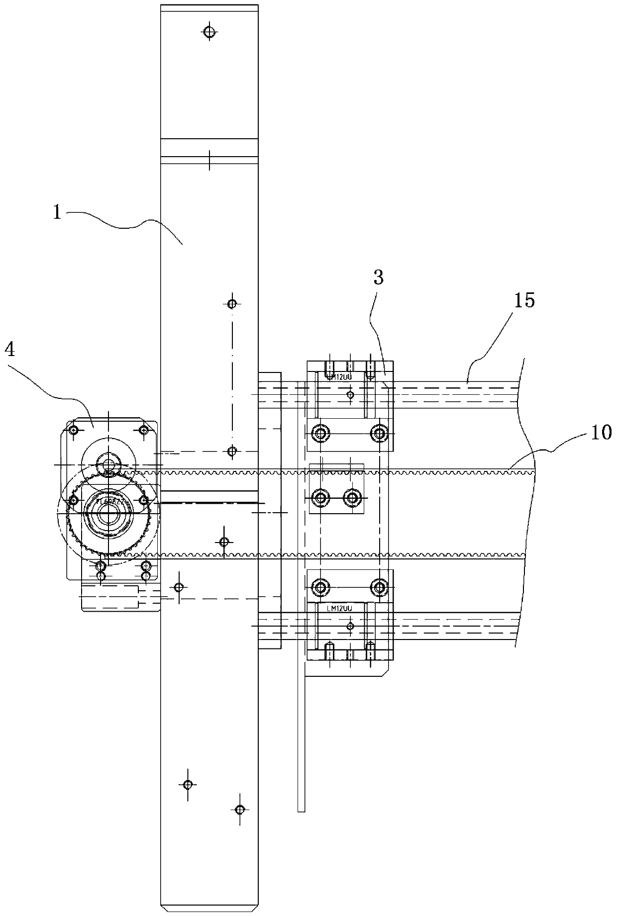
[0018] The transmission assembly 4 includes a transmission frame 6, and a stepping motor 7 is arranged in the transmission frame 6, and the stepping motor 7 drives a large gear 8 for meshing transmission, and the large gear 8 drives a driving end belt tooth 9 rotates;

[0019] The two driving end belt teeth 9 are connected by a synchronous belt 10;

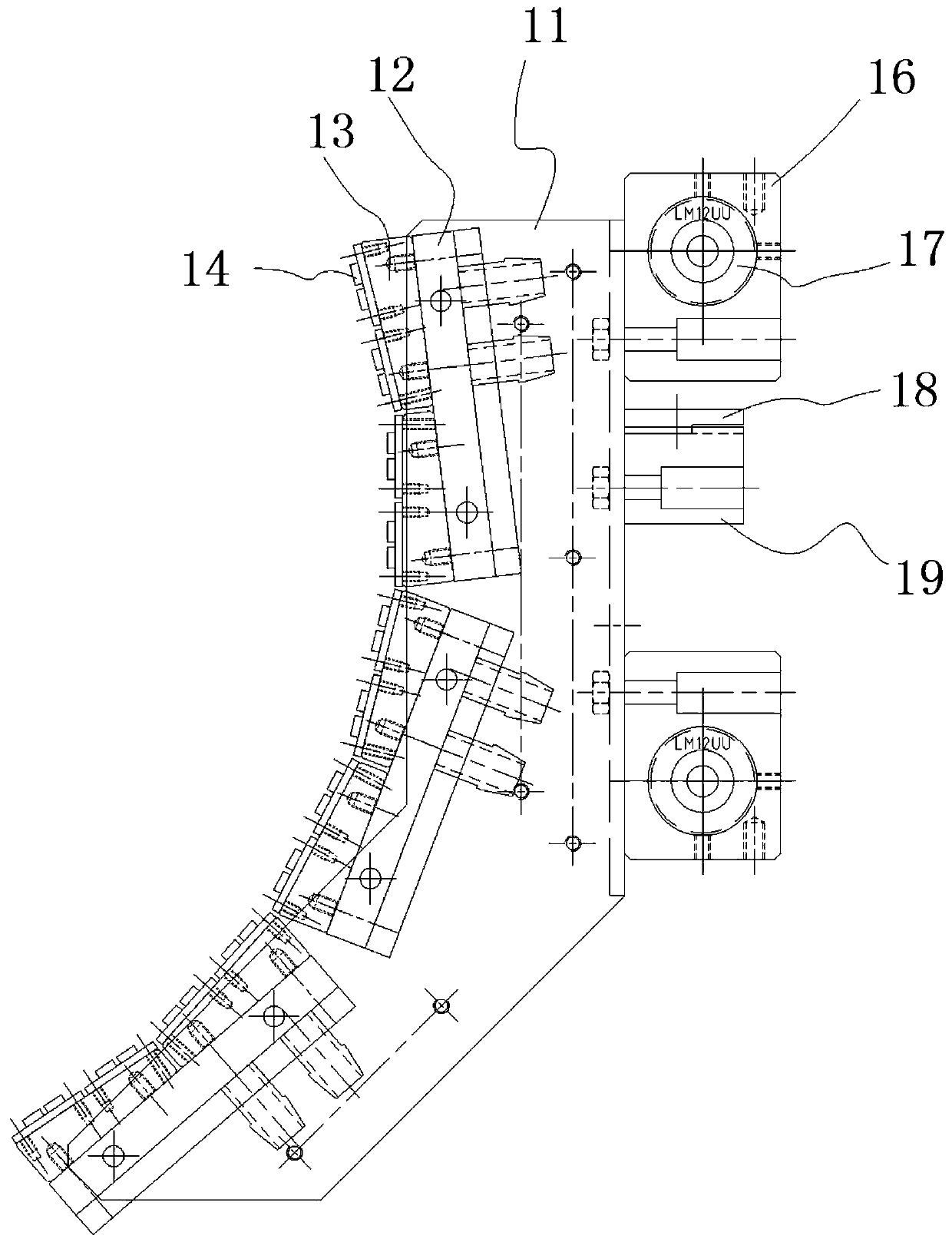
[0020] The executive assembly 3 includes an exposure bracket 11, and the exposure bracket 11 is displaced between the wall panels 1 through the timing belt 10. The outer wall of the exposure bracket 11 is...


PUM


Abstract

The invention relates to an exposure mechanism, in particular to an exposure mechanism of a plate making machine. The mechanism comprises a wall plate and a light drum, a displaceable execution assembly is arranged in the wall plate, transmission assemblies are arranged at the two side ends of the wall plate respectively, the transmission assemblies drive the execution assembly to displace, and the execution assembly is in movable contact with the light drum. The exposure speed of the plate is greatly increased, and the production efficiency is improved.

Description

technical field [0001] The invention relates to an exposure mechanism, in particular to an exposure mechanism of a plate making machine. Background technique [0002] After the plate making of the traditional plate making machine is completed, the plate needs to be put into another exposure device outside the plate making machine for exposure, that is, the plate needs to be manually taken out of the plate making machine and then put into another exposure device for exposure. There will also be various unexpected factors affecting the quality of the version. The more versions there are, the more difficult it will be to expose. Exposure is a necessary step in plate making. If the plate is not exposed, the plate will return to its original color after plate washing. However, such an entire exposure process is relatively complicated, requires a lot of manpower and material resources, and the production efficiency is relatively low. Therefore, there is an urgent need for a new...

Claims


Application Information

Patent Timeline
IPC IPC(8): G03B27/26G03B27/10
CPCG03B27/10G03B27/26
Inventor 赵骄佑陈懿董海丁建
Owner HANGZHOU CRON MACHINERY & ELECTRONICS CO LTD
Why Eureka
Try Eureka