
Method and device for determining infill well location in complex fault-block reservoir production area

A technology for oil reservoir exploitation and complex fault blocks, which is applied in the direction of production fluid, wellbore/well components, earthwork drilling and production, etc., can solve the problems of no well pattern, difficult well location, small production area, etc., and achieve improvement The effect of the degree of production of reserves

Active Publication Date: 2022-04-19
CHINA UNIV OF PETROLEUM (BEIJING)
View PDF3 Cites 0 Cited by
  • Summary
  • Abstract
  • Description
  • Claims
  • Application Information

AI Technical Summary

Problems solved by technology

However, the production area of ​​complex fault-block reservoirs is usually small, and generally there is no clear well pattern, so it is difficult to determine the well location of infill wells by conventional methods
Even if there is an obvious well pattern in the production area of ​​complex fault-block reservoirs, there are often multiple oil layers and multiple sets of oil-water systems underground in this area, and infill wells selected and deployed by conventional methods cannot better achieve the purpose of improving the production of reserves

Method used


Image

  • Method and device for determining infill well location in complex fault-block reservoir production area
  • Method and device for determining infill well location in complex fault-block reservoir production area
  • Method and device for determining infill well location in complex fault-block reservoir production area

Examples


Embodiment Construction

[0027] In order to make the purpose, technical solutions, and advantages of the embodiments of the present application clearer, the embodiments of the present application will be further described in detail below in conjunction with the accompanying drawings. Here, the exemplary embodiments of the application and their descriptions are used to explain the application, but not to limit the application.

[0028] At present, the selection of infill wells in complex fault-block reservoirs lacks general quantitative and detailed calculation methods, which often results in relatively large remaining oil saturation in some oil layers in complex fault-block reservoirs, while other oil layers have low remaining oil saturation or have been watered out , the development is uneven, the subsequent conversion of the development model is difficult, and the economic benefits are low. Therefore, the conventional well location selection method is not completely suitable for multi-layer complex ...


PUM


Abstract

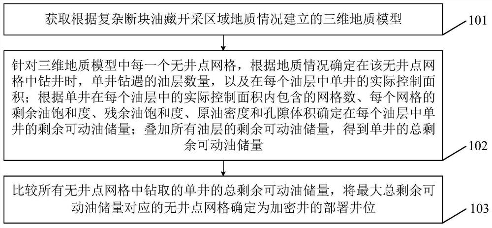
The present application discloses a method and device for determining the location of an infill well in the production area of ​​a complex fault-block oil reservoir. The method includes: obtaining a three-dimensional geological model of the production area of ​​a complex fault-block oil reservoir; According to the geological conditions, when drilling in the grid without well points, the number of oil layers drilled by a single well and the actual control area of ​​a single well in each oil layer are determined; according to the actual control area of ​​a single well in each oil layer The number of grids included, the remaining oil saturation of each grid, the residual oil saturation, crude oil density and pore volume determine the remaining movable oil reserves of a single well in each reservoir; the remaining movable oil of all reservoirs is superimposed Reserves, the total remaining movable oil reserves of a single well are obtained; the grid without well points corresponding to the maximum total remaining movable oil reserves is determined as the deployment well location of infill wells. The application can determine the well position of the infill well through a reasonable method, and improve the reserve producing degree of the complex fault block oil reservoir development area.

Description

technical field [0001] The present application relates to the technical field of petroleum exploration and development, in particular to a method and device for determining the location of an infill well in a complex fault-block oil reservoir exploitation area. Background technique [0002] This section is intended to provide a background or context to embodiments of the invention that are recited in the claims. The descriptions herein are not admitted to be prior art by inclusion in this section. [0003] Complex fault-block oil reservoirs have large reserves in the world's oil reserves. The faults in complex fault-block oil reservoirs are numerous and complex, and the oil reservoirs are cut into many fault blocks with different sand bodies. Complex fault-block reservoirs have small and complex oil-bearing areas, have multiple oil-water systems, and each oil-water system has different reservoir characteristics and formation structures, and usually lacks natural energy. Am...

Claims


Application Information

Patent Timeline
Patent Type & Authority Patents(China)
IPC IPC(8): G06T17/05G06Q50/02E21B43/30
CPCG06T17/05G06Q50/02E21B43/30E21B43/305
Inventor 张波刘慧卿叶继根
Owner CHINA UNIV OF PETROLEUM (BEIJING)
Learn More