Dynamic light source disinfection unit and disinfection cabinet applying same

A light source and dynamic technology, applied in the field of disinfection cabinets, can solve the problems of fixation, the existence of disinfection dead ends, and three-dimensional space dead ends.

Pending Publication Date: 2020-05-01
NINGBO FOTILE KITCHEN WARE CO LTD
View PDF5 Cites 0 Cited by
  • Summary
  • Abstract
  • Description
  • Claims
  • Application Information

AI Technical Summary

Problems solved by technology

[0005] First, the installation position of the ultraviolet light source is fixed, and the effective disinfection effect is achieved by adopting a multi-directional arrangement method. However, in this scheme, the installation position of the ultraviolet light source is fixed, and the disinfection area is correspondingly fixed, and there are dead spots for disinfection;
[0006] Second, similar to the scheme of the above-mentioned ultraviolet lamp tube, the ultraviolet light source is integrated into a disinfection module, and the whole disinfection module is moved or / and rotated to perform multi-angle disinfection. The above-mentioned mobile disinfection module reduces disinfection to some extent. Dead angle, but the movement or rotation of the overall module only solves the two-dimensional dead angle on the plane parallel to the disinfection module. Since the plates and dishes have a certain arc, even if the disinfection module rotates or moves, there is still a three-dimensional dead angle.

Method used


Image

  • Dynamic light source disinfection unit and disinfection cabinet applying same
  • Dynamic light source disinfection unit and disinfection cabinet applying same
  • Dynamic light source disinfection unit and disinfection cabinet applying same

Examples


Embodiment 1

[0055] like Figure 1 to Figure 5 Shown is the first preferred embodiment of the disinfection cabinet using the dynamic light source disinfection unit of the present invention.

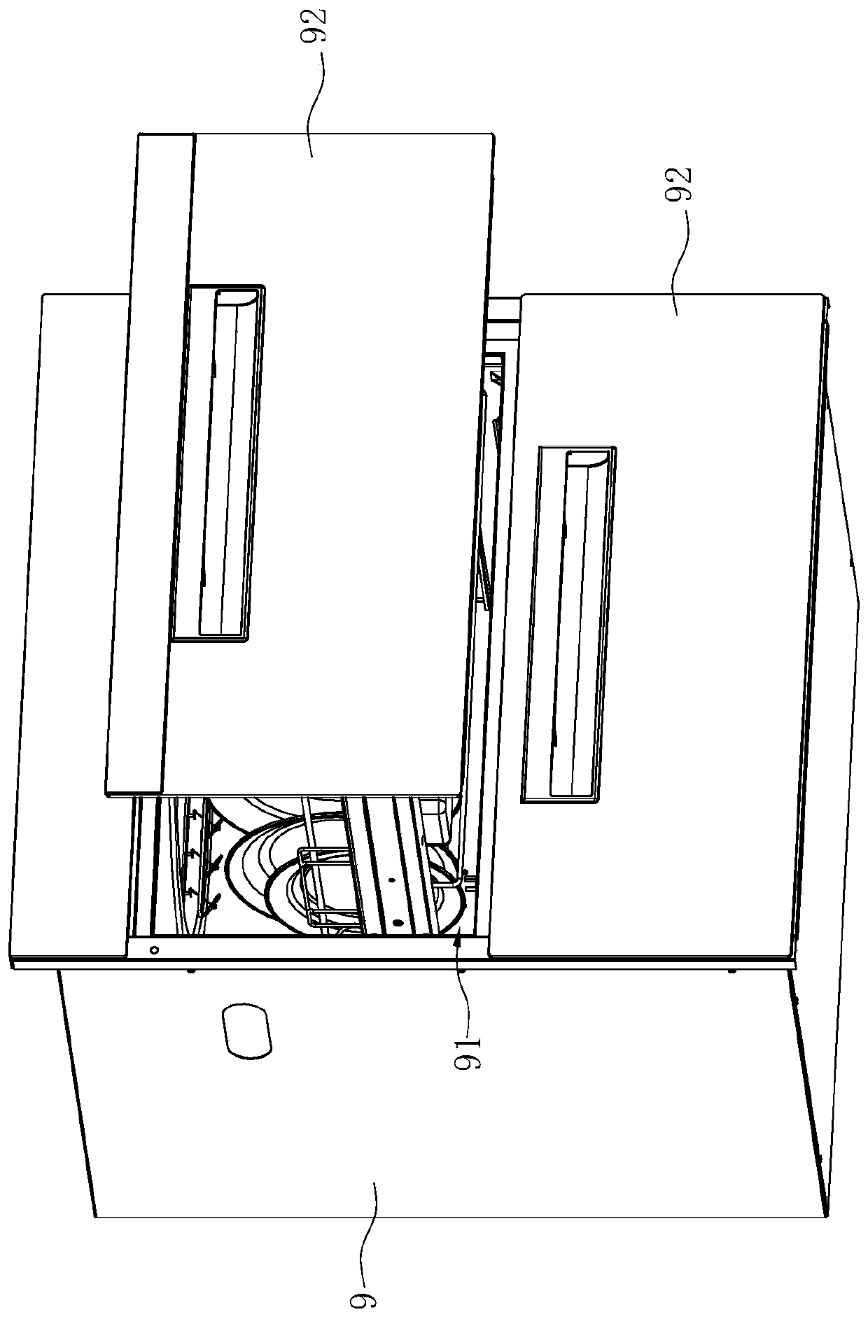
[0056] like figure 1 and figure 2 As shown, the disinfection cabinet includes a cabinet body 9 with a disinfection chamber 91 , a dynamic light source disinfection unit 100 disposed on the cabinet body 9 , and a drawer 92 capable of entering and exiting the disinfection chamber 91 .

[0057] Wherein, the quantity of the drawer 92 is two, and is arranged in the disinfection cavity 91 one above the other respectively.

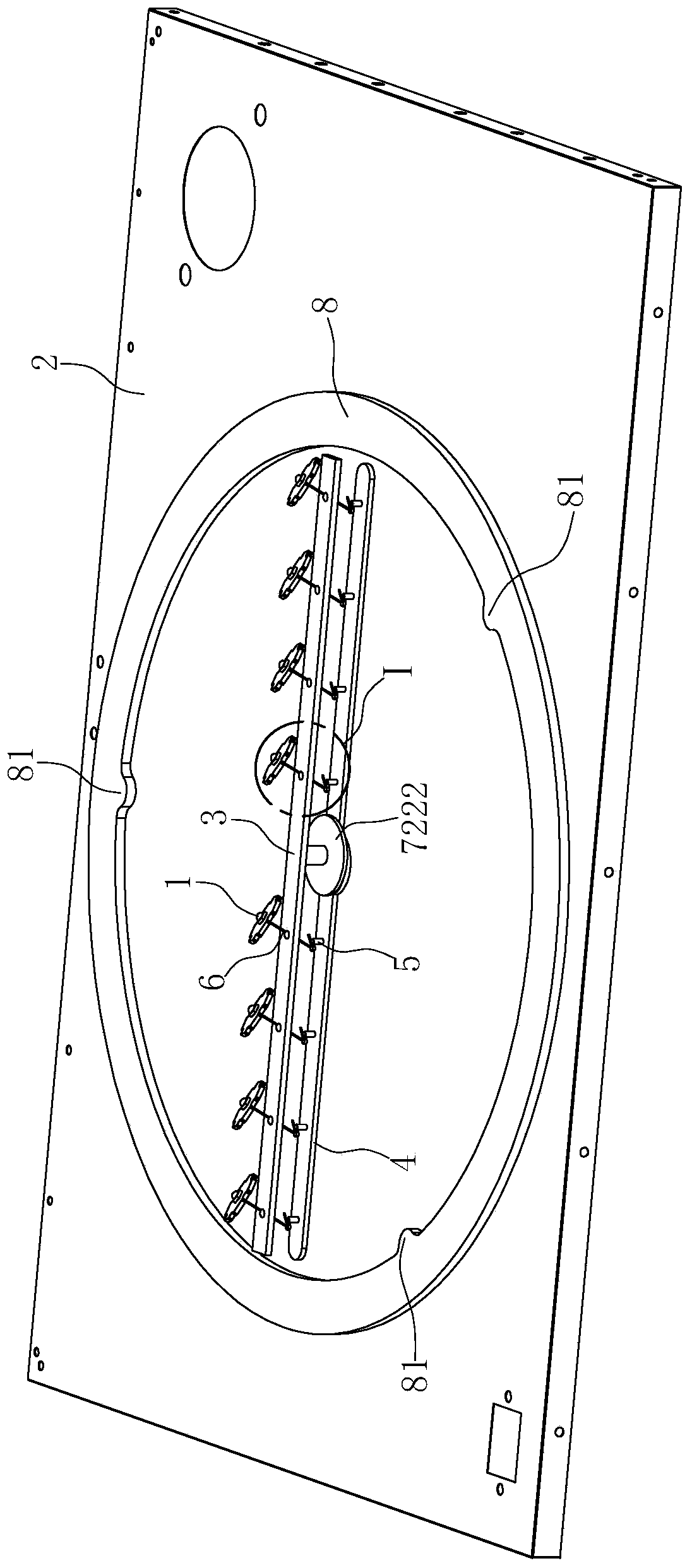
[0058] like Figure 3 to Figure 6 As shown, the dynamic light source disinfection unit 100 includes a plurality of disinfection light sources 1, a panel 2, a rotating plate 3 rotatably arranged on the panel 2, a guide strip 4 between the panel 2 and the rotating plate 3, and the disinfection light source 1 One-to-one correspondence is used to install the connecting seat 5 and the co...

Embodiment 2

[0071] like Figure 1 to Figure 5 Shown is the second preferred embodiment of the disinfection cabinet using the dynamic light source disinfection unit of the present invention. The difference with Example 1 is:

[0072] In this embodiment, the guide strip 4 is replaced by the installation strip 4', and the installation strip 4' is arranged side by side with the rotating plate 3, and both of them are arranged on the panel 2 through the rotating shaft 7221 so as to be able to rotate synchronously, without setting the support plate 7222.

[0073] Connecting seat 5 is replaced by guide gear 5 ', and this guide gear 5 ' is rotatably connected on mounting bar 4 ', and the second end of connecting rod 6 is installed in its eccentric position, and the second universal rotation ball 62 need not be set. There are two groups of guide gears 5', which are respectively located on both sides of the rotating shaft 7221. For each set of guide gears 5', the number of guide gears 5' is four, a...


PUM


Abstract

The invention discloses a dynamic light source disinfection unit. The dynamic light source disinfection unit is characterized by comprising a rotating plate (3) provided with a through hole (31), a connecting rod (6) arranged in the through hole (31) of the rotating plate (3) in a penetrating mode, a disinfection light source (1) arranged at the first end of the connecting rod (6), a first drivingmechanism (7) and a second driving mechanism, wherein the first driving mechanism (7) is used for driving the rotating plate (3) to rotate; and the second driving mechanism is used for driving the second end of the connecting rod (6) to rotate around the central axis of the through hole (31) relative to the rotating plate (3), so the disinfection light source (1) also rotates around the central axis of the through hole (31) under the driving of the connecting rod (6). The invention also discloses a disinfection cabinet applying the dynamic light source disinfection unit. Compared with the prior art, the dynamic light source disinfection unit enables ultraviolet rays to be uniformly distributed through combined movement of two rotating modes.

Description

technical field [0001] The invention relates to the technical field of kitchen equipment, in particular to a dynamic light source disinfection unit and a disinfection cabinet using the dynamic light source disinfection unit. Background technique [0002] Most of the disinfection cabinets currently on the market are high temperature or ozone disinfection. Occasionally, ultraviolet disinfection cabinets are combined with high temperature or ozone, and there are few independent ultraviolet disinfection cabinets. The reason is that the disinfection range of ultraviolet light disinfection in the cabinet is limited. It is easy to cause incomplete disinfection and has certain defects. [0003] In order to solve the above problems, the patent application number CN201710922611.5 (announcement number is CN109589425A) of the invention patent "A Disinfection Device and a Disinfection Cabinet Using the Disinfection Device" discloses a disinfection device and a disinfection device using t...

Claims


Application Information

Patent Timeline
Patent Type & Authority Applications(China)
IPC IPC(8): A61L2/10A61L2/26
CPCA61L2/10A61L2/26
Inventor 张晓静杨历
Owner NINGBO FOTILE KITCHEN WARE CO LTD
Why Eureka
Try Eureka