Groove pin structure of warp knitting machine

A technology of warp knitting machine and grooved needles, which is applied in warp knitting, knitting, textiles and papermaking, etc. It can solve the problems of synchronous forward movement of the cloth surface, easy damage of the grooved needles, and large resistance of the grooved needles, achieving small resistance, Not easy to damage, high speed effect

Active Publication Date: 2011-04-13
南通金威复合材料有限公司
View PDF0 Cites 0 Cited by
  • Summary
  • Abstract
  • Description
  • Claims
  • Application Information

AI Technical Summary

Problems solved by technology

However, for multi-axial fabrics with relatively high weaving density and thick thickness, since the grooved needles move up and down and cannot move forward synchronously with the fabric surface, the resistance of the grooved needles is relatively large, and the grooved needles are easily damaged.

Method used


Image

  • Groove pin structure of warp knitting machine
  • Groove pin structure of warp knitting machine
  • Groove pin structure of warp knitting machine

Examples


Embodiment 1

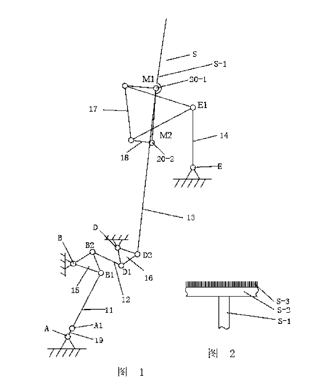
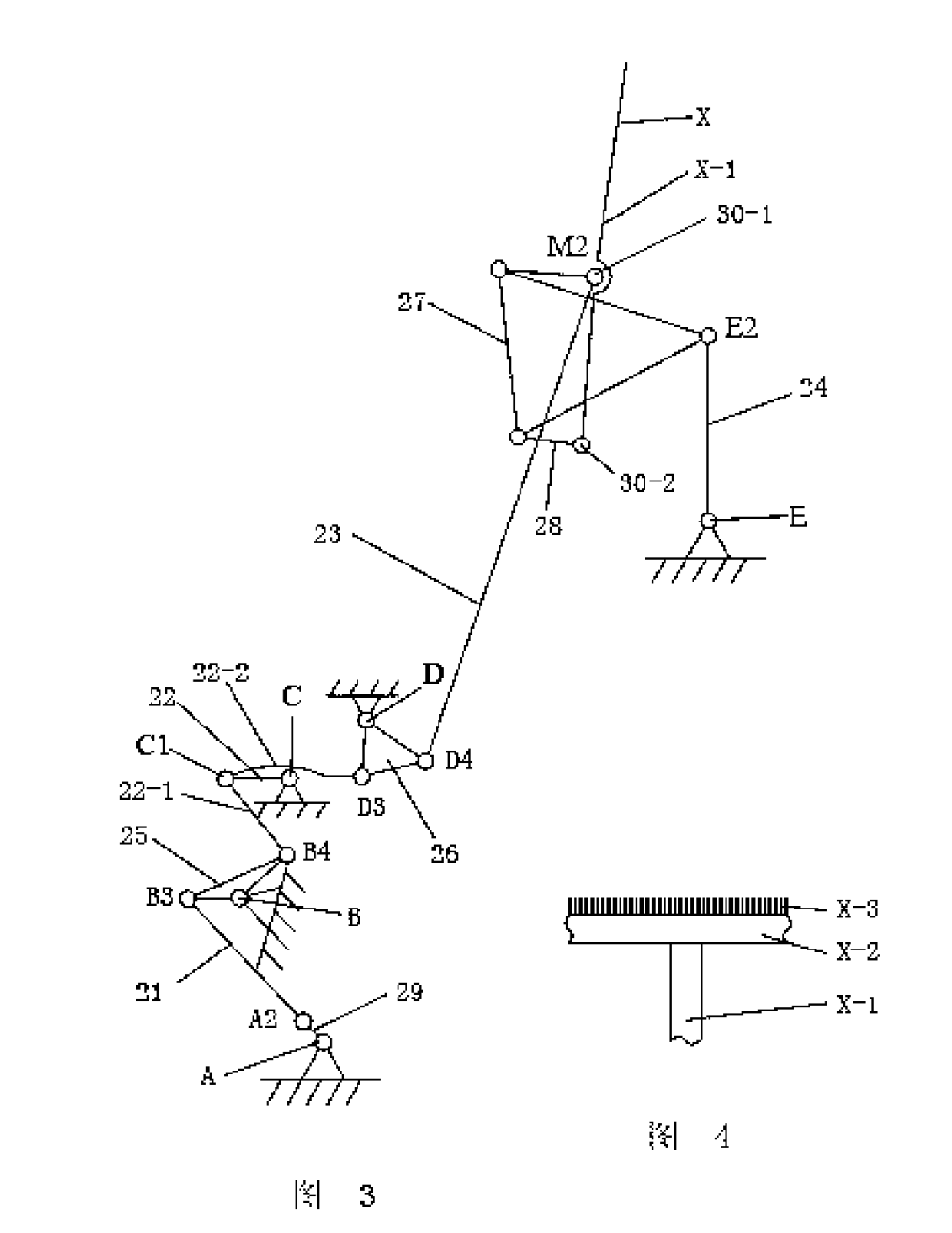
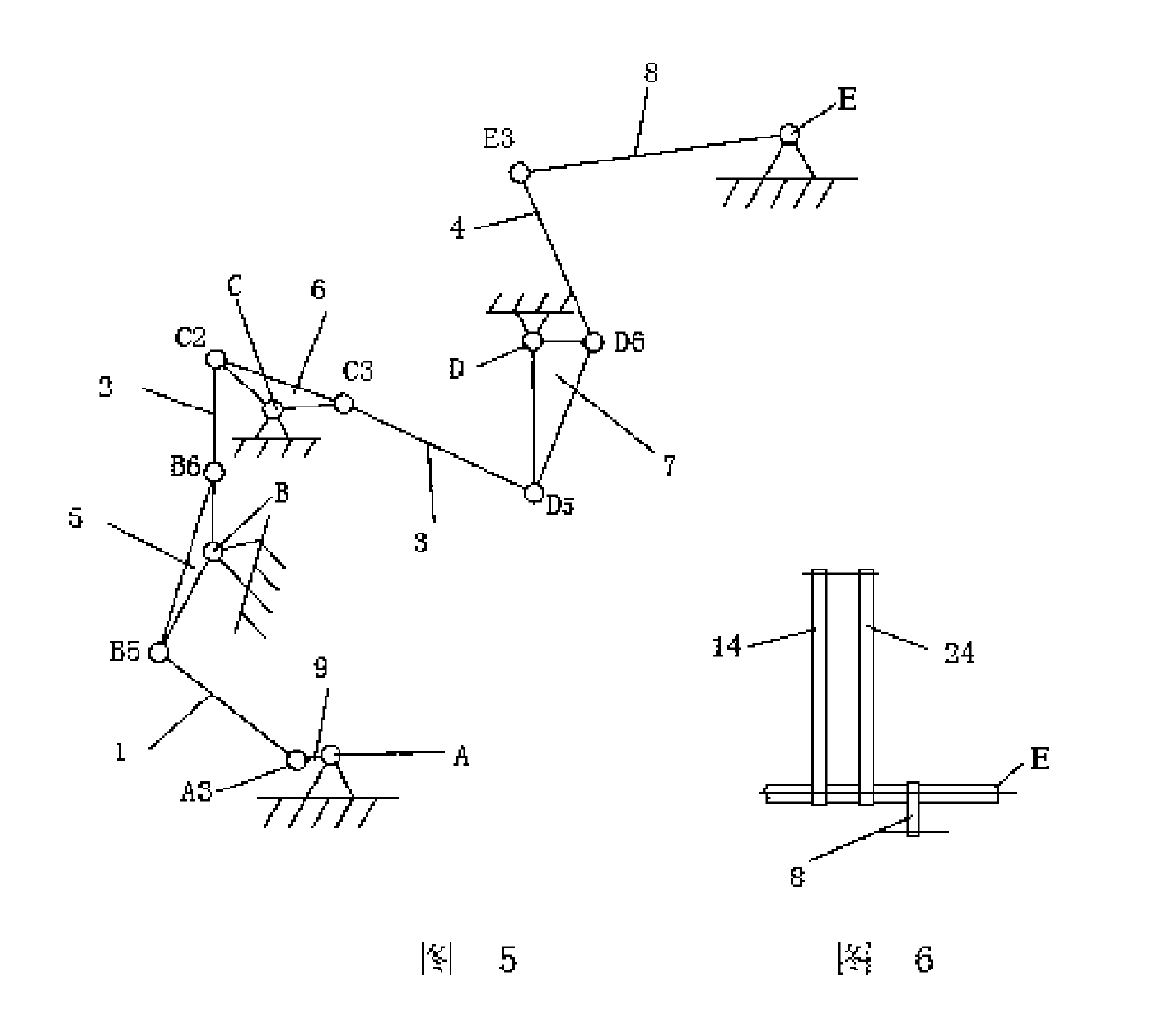
[0026] The embodiment shown in the drawings includes a main shaft A, a needle body assembly S and a needle core assembly X, and the needle body assembly S and the needle core assembly X are respectively driven by the needle up and down movement mechanism and the needle core up and down movement mechanism. In addition, it also includes a front and rear movement mechanism, No. 1 long pin shaft B, No. 2 long pin shaft C, No. 3 long pin shaft D and swing shaft E. Above-mentioned main shaft A, No. 1 long pin shaft B, No. 2 long pin shaft C, and No. 3 long pin shaft D are in the oil tank of the warp knitting machine and are respectively supported by a support. The swing axis E is supported by a bracket fixed to the top of the tank. Main shaft A, No. 1 long pin shaft B, No. 2 long pin shaft C, No. 3 long pin shaft D and swing shaft E are long shafts equal to the width of the machine. The main shaft A is the power input shaft of the main movement of the warp knitting machine, driven ...


PUM


Abstract

The invention discloses a groove pin structure of a warp knitting machine. The groove pin structure comprises a main shaft, a pin body assembly and a pin core assembly, wherein the pin body assembly and the pin core assembly are driven by a pin body vertical movement mechanism and a core pore vertical movement mechanism to perform vertical movement and driven by a longitudinal movement mechanism to perform longitudinal movement, thus the compound movement of the groove pin can be realized. The device can synchronously move forward with cloth cover, so the groove pin has small resistance and is not easy to damage and is particularly suitable for knitting multi-axial textiles with higher density and thicker thickness. The device takes a plane link mechanism as a main member, has simple structure and low cost and is suitable for warp knitting machines with higher operating speed.

Description

technical field [0001] The present invention relates to a warp knitting machine slot needle device. Background technique [0002] The non-buckling yarn layers (cloth surface) of different axial directions laid in several layers are sewn together with knitting needles to form a multi-axial fabric. Here, slotted needles are used, and the slotted needles are compound needles. It consists of two independent parts, the needle body and the needle core, and there are requirements for coordination between their movements. Needle body mechanism and needle core mechanism see Figure 8 and Figure 9 . In the process of stitching the non-buckling yarn layer, the compound needle needs to pierce through the yarn layer first, hook the sewing thread and then form a loop. During this process, the cloth surface always moves forward continuously. Generally, the grooved needle movement mechanism on the grooved needle type warp knitting machine drives the grooved needle to move up and down, r...

Claims


Application Information

Patent Timeline
Patent Type & Authority Patents(China)
IPC IPC(8): D04B27/06D04B27/08
Inventor 曹清林
Owner 南通金威复合材料有限公司
Why Eureka
Try Eureka