Quick lifting spare wheel frame with high anti-theft performance

A technology of high anti-theft and spare tire rack, which is applied in the direction of spare tire arrangement, transportation and packaging, vehicle parts, etc., can solve the problems of high production cost, long bevel distance, small use range, etc., and achieve low production cost and high safety Improvement and anti-theft ability

Pending Publication Date: 2020-05-01
郜慧
View PDF0 Cites 0 Cited by
  • Summary
  • Abstract
  • Description
  • Claims
  • Application Information

AI Technical Summary

Problems solved by technology

[0003] The commercial vehicle spare tire rack with the anti-theft and all-weather fast lifting function that the applicant previously applied for with the application number 2014101316849 preliminarily solved the above problems, but in the process of use, new problems appeared, such as the locking mechanism including the first connection The plate, the first lock piece, the second lock piece, the second connecting plate, the third lock piece, the fourth lock piece, the fixing frame, the chute, the spring seat, the spring and many other parts, including four lock holes, are combined during production Several processes such as drilling, tapping, stamping, welding and calibration are required before, the structure is complex, the production process is complicated, and the production cost is high; because the brackets are respectively fixed under the bottom plate in an inclined shape through suspension, the distance between the hypotenuses is long, As a result, the suspension distance cannot be less than 170mm, plus the diameter of the suspension head, so when the diameter of the center hole of the wheel hub is less than 190mm, it cannot be used. It can only be used for the spare tire of heavy commercial vehicles. The scope of use is small, and the spare tire of many models cannot be used. Use and many other problems, therefore, its improvement and innovation is imperative

Method used


Image

  • Quick lifting spare wheel frame with high anti-theft performance
  • Quick lifting spare wheel frame with high anti-theft performance
  • Quick lifting spare wheel frame with high anti-theft performance

Examples


Embodiment Construction

[0041] The specific implementation manners of the present invention will be described in further detail below in conjunction with the accompanying drawings.

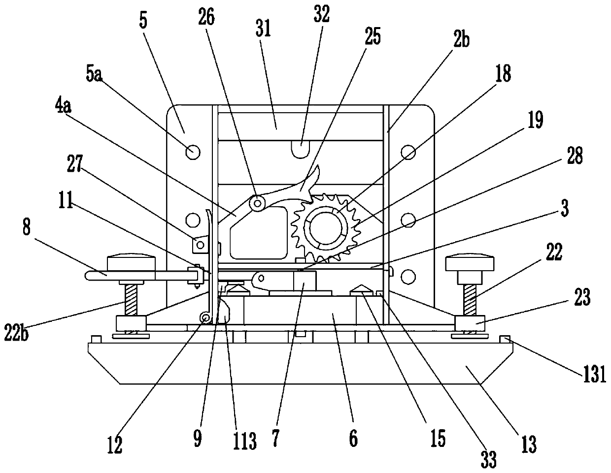
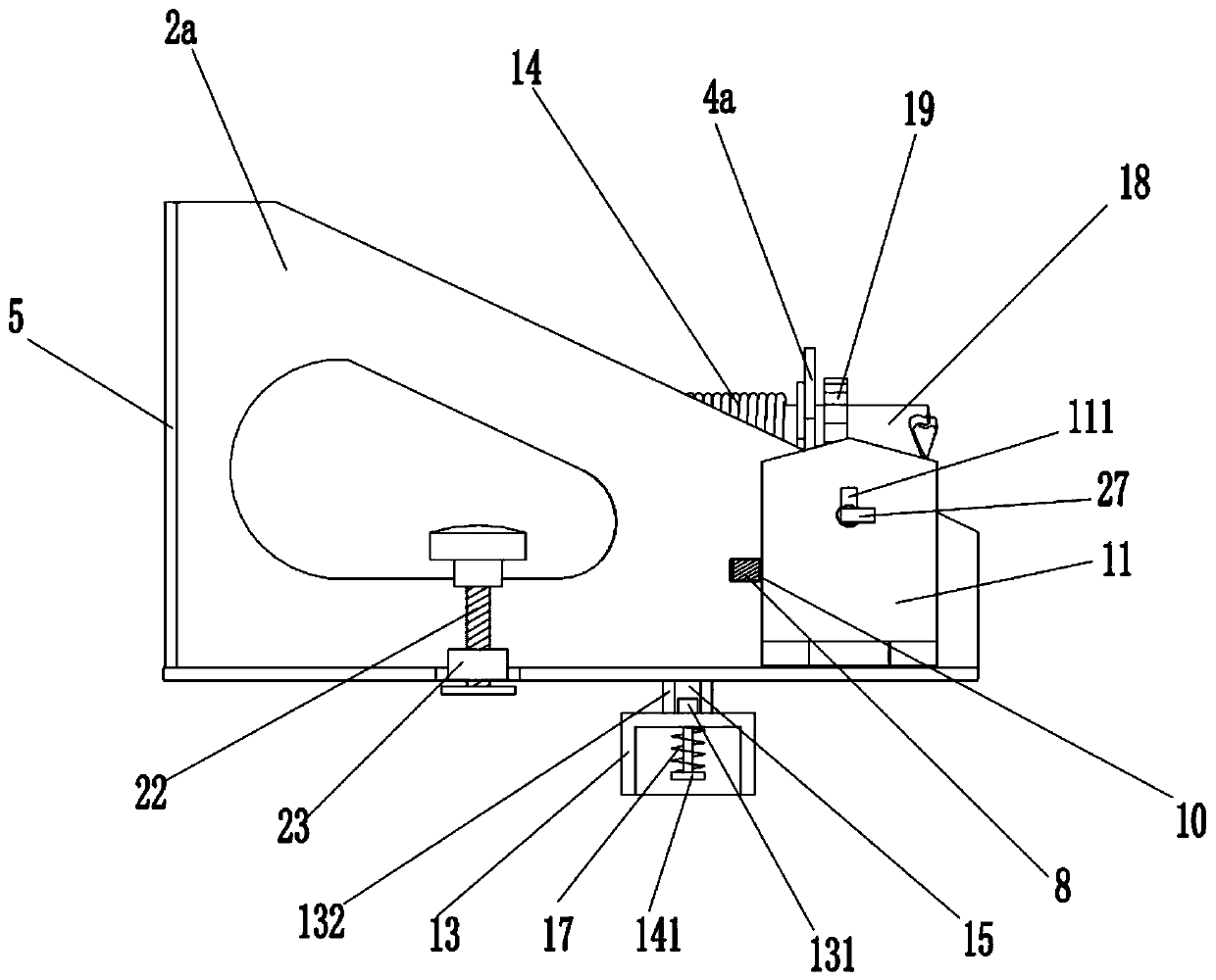
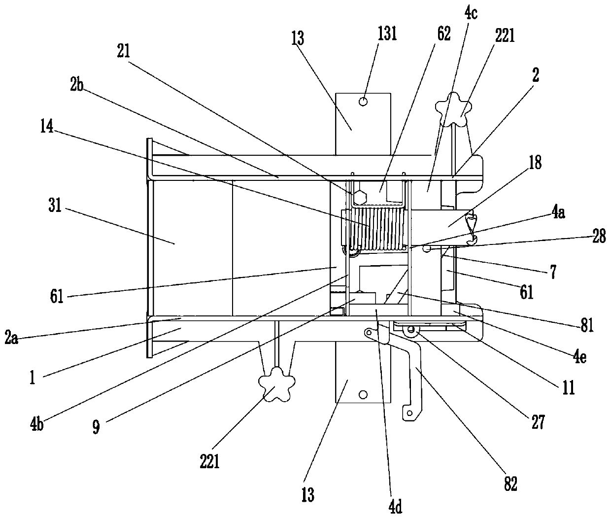
[0042] Depend on Figure 1-25 It is given that the present invention has a high anti-theft fast lifting spare tire rack, including a bracket 13, a bottom plate 1, a locking mechanism and a rope shaft 18, and the upper and lower sides of the bottom plate 1 are respectively equipped with symmetrical first sides. Plate 2a and the second side plate 2b, between the first side plate 2a and the second side plate 2b, the first rope shaft support plate 4a and the second rope shaft support plate 4b vertically arranged alternately are installed above the bottom plate 2, the second rope shaft support plate 4b A rope shaft support plate 4a and the second rope shaft support plate 4b are rotatably connected with a horizontal rope shaft 18, and the locking mechanism is arranged on the bottom plate below the rope shaft 18. The locking me...


PUM


Abstract

The invention relates to a quick lifting spare wheel frame with high anti-theft performance. The technical scheme is that a locking mechanism is arranged on a bottom plate below a rope shaft, and comprises a left assembly and a right assembly; one side of the upper surface of the left assembly is hinged to a locking trigger arm extending towards the right assembly; the hinged end of the locking trigger arm is connected with a trigger plate extending towards the side surface; when a release rod in a sliding release groove is positioned at the leftmost end of the sliding release groove, the leftassembly and the right assembly are tightly attached together in a face-to-face mode; And a lifting pin is clamped in a lifting pin locking hole, and the upper end of the lifting pin on the same sidebears against the trigger plate to support the locking trigger arm. According to the invention, the quick lifting spare wheel frame is high in anti-theft capacity, capable of being rapidly released and automatically locked, capable of disassembling and assembling a spare wheel within several seconds, wide in vehicle model application range, low in production cost, simple in process and long in service life, can substantially improve the safety of high-value tires through the anti-theft design, and is an innovation on the spare wheel frame.

Description

technical field [0001] The invention relates to a spare tire rack, in particular to a fast lifting spare tire rack with high anti-theft performance. Background technique [0002] The car spare tire rack is used to install the spare tire of the car so that the spare tire can be replaced in case of a car blowout or other unexpected situations. The existing spare tire racks are mostly hinge type and worm gear type. , time-consuming and laborious, low work efficiency, easy to be stolen, and extremely inconvenient to use. In addition, the disorderly winding of the steel wire rope of the spare tire rack is a problem that the world's automobile industry has not solved for many years. Therefore, the problem of the fixed hole when the tire is lifted up and the sudden stop in mid-air when the tire is put down have long caused the problem of frequent broken ropes. It has become a chronic disease that makes the majority of drivers a headache. For example, 1. During the lifting process...

Claims


Application Information

Patent Timeline
Patent Type & Authority Applications(China)
IPC IPC(8): B62D43/00
CPCB62D43/007
Inventor 郜世光郜慧
Owner 郜慧
Why Eureka
Try Eureka