

A switchgear moving end assembly and switchgear
A switch device and moving end technology, which is applied to air switch components, electric switches, electrical components, etc., can solve problems such as easy swing, excessive impulse, and accidents, so as to improve movement difficulty, reduce impulse, and avoid glitch effect
- Summary
- Abstract
- Description
- Claims
- Application Information
AI Technical Summary
Problems solved by technology
Method used
Image

Examples
Embodiment Construction
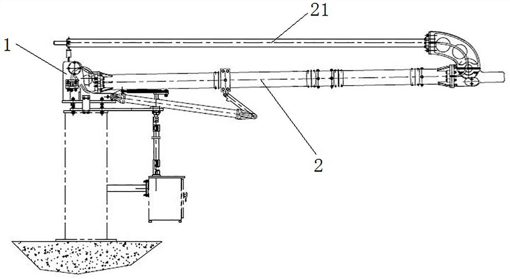
[0052] In the present invention, the switch device includes a static contact, a moving end assembly, and a moving contact disposed at the end of the moving end assembly. During operation, through the action of the moving end assembly, the static contact and the moving contact can be contacted for conduction or separated and broken. open. The switch device may specifically be an isolating switch or a grounding switch.
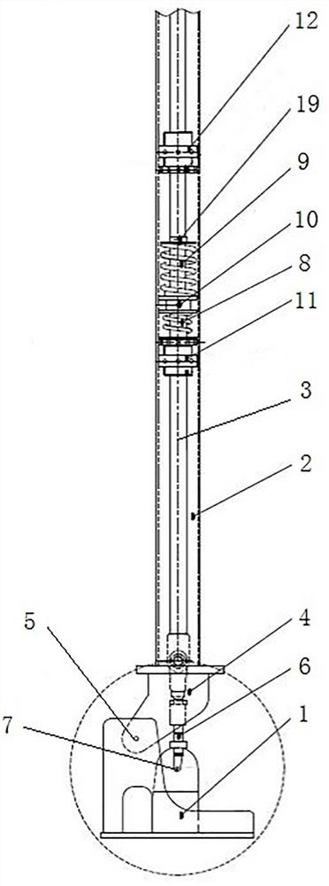
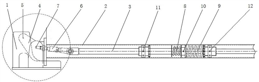
[0053] Embodiment 1 of the switch device in the present invention, in this embodiment, as follows figure 1 Taking the vertical telescopic grounding switch shown as an example, the structure and working principle of the switch device in this application will be introduced. The grounding switch includes a moving end assembly, and the structure of the moving end assembly, such as figure 1 and figure 2 As shown, the movable end assembly includes a base 1, a lower conductive tube 2, the lower conductive tube 2 is hinged on the base 1, the upper end of the lower c...
PUM
 Abstract
Description
Claims
Application Information