Shield of base station antenna

A technology for base station antennas and shields, which is applied to antennas, antenna parts, antenna supports/installation devices, etc., and can solve the problems of inconvenient replacement of radiators, etc.

Pending Publication Date: 2020-05-01
COMMSCOPE TECH LLC
View PDF0 Cites 2 Cited by
  • Summary
  • Abstract
  • Description
  • Claims
  • Application Information

AI Technical Summary

Problems solved by technology

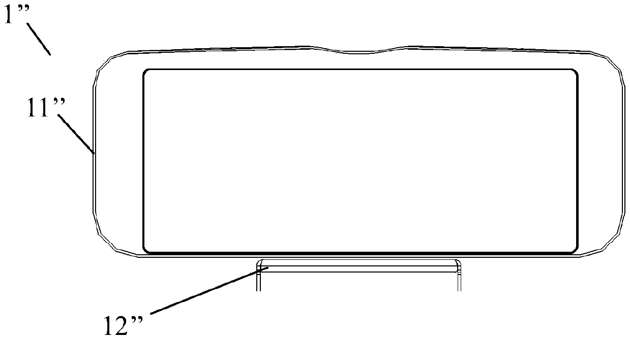
Since the cover 11" cannot be disassembled from the bracket 12", it is inconvenient to replace the radiator in the cover 11"

Method used


Image

  • Shield of base station antenna
  • Shield of base station antenna
  • Shield of base station antenna

Examples


Embodiment Construction

[0039] The present disclosure will be described below with reference to the accompanying drawings, which illustrate several embodiments of the disclosure. However, it should be understood that the present disclosure can be presented in many different ways, and is not limited to the embodiments described below; in fact, the embodiments described below are intended to make the disclosure of the present disclosure more complete and contribute to this Those skilled in the art fully explain the protection scope of the present disclosure. It should also be understood that the embodiments disclosed herein can be combined in various ways to provide even more additional embodiments.

[0040] It should be understood that like reference numerals refer to like elements throughout the drawings. In the drawings, the dimensions of some features may be distorted for clarity.

[0041] It should be understood that the terminology used in the specification is for the purpose of describing part...


PUM


Abstract

The invention discloses a shield for a base station antenna. The shield comprises a shield body and a support, wherein the shield body stretches across a radiator of the base station antenna and comprises a front wall, a first side wall, a second side wall, a first rear flange and a second rear flange, wherein the first side wall and the second side wall extend backwards from the front wall, the first rear flange and the second rear flange extend inwards from the corresponding first side wall and second side wall, the support includes a body, and a first mounting flange and a second mounting flange extending forward from the body, the first mounting flange and the second mounting flange are matched with the corresponding first rear flange and the corresponding second rear flange of the cover body so as to connect the shield body to the support. The shield is advantaged in that appearance of the shield is attractive, and the possibility of screw loosening caused by lateral wind force isfurther reduced.

Description

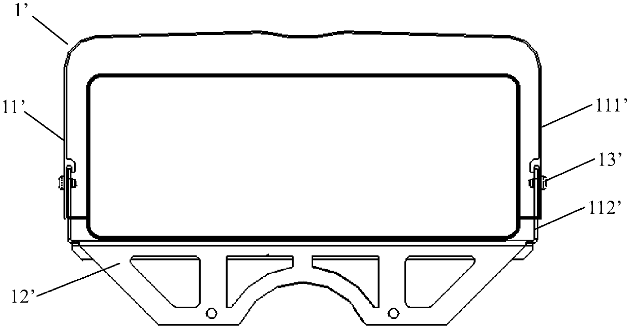
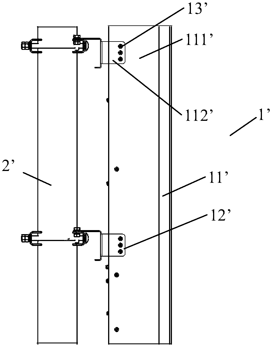
technical field [0001] The present disclosure relates generally to the field of base station antennas. More specifically, the present disclosure relates to a shroud for a base station antenna. Background technique [0002] In outdoor environments, base station antennas are mounted on communication towers using antenna mounts. In order to protect the radiator of the base station antenna from the harsh outdoor environment, a shield is usually placed on the radiator. There are currently two main types of shrouds, open shrouds and closed shrouds. [0003] Figure 1A and 1B A sectional view and a side view of a conventional open shroud 1' are shown respectively. The shield 1' comprises a cover body 11' and a bracket 12'. Bracket 12' is used to secure cover 11' to antenna mount 2' on a communication tower (not shown). The side wall 111' of the cover 11' partially overlaps the connecting wall 121' of the bracket 12', and is fastened together by screws 13', thereby installing ...

Claims


Application Information

Patent Timeline
Patent Type & Authority Applications(China)
IPC IPC(8): H01Q1/42H01Q1/12H01Q1/24
CPCH01Q1/42H01Q1/1207H01Q1/246H01Q1/1228H01Q1/002
Inventor 陈晨唐普亮许国龙
Owner COMMSCOPE TECH LLC
Why Eureka
Try Eureka