Supercharge Your Innovation With Domain-Expert AI Agents!

A kind of rohc compressor and its compression state adjustment method

A technology of compression state and adjustment method, applied in the direction of using signal quality detector for error detection/prevention, digital transmission system, error prevention, etc., which can solve problems such as reducing compression rate and increasing header

Active Publication Date: 2020-10-27
ASR SMART TECH CO LTD
View PDF7 Cites 0 Cited by
  • Summary
  • Abstract
  • Description
  • Claims
  • Application Information

AI Technical Summary

Problems solved by technology

The NACK-type feedback packet (Feedback) will trigger the ROHC compressor to fall back from the high-order compression state to the low-order compression state, and the header generated by compression will increase, thereby reducing the compression ratio

Method used


Image

  • A kind of rohc compressor and its compression state adjustment method
  • A kind of rohc compressor and its compression state adjustment method
  • A kind of rohc compressor and its compression state adjustment method

Examples


Embodiment 1

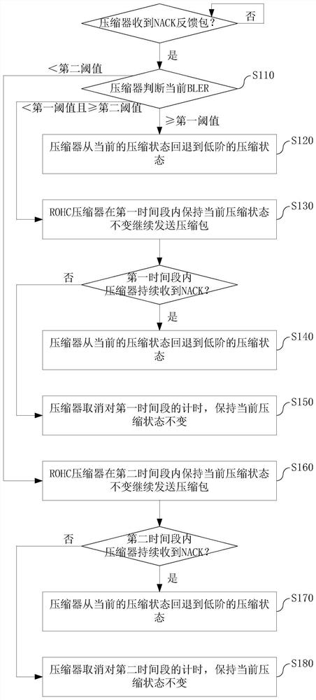
[0027] see figure 1 , which is Embodiment 1 of the method for adjusting the compression state of the ROHC compressor provided in the present application, including the following steps.

[0028] Step S110: When the ROHC compressor receives the negative response data packet sent by the ROHC decompressor, judge the data block error rate (BLER, Block Error Rate) of the current air interface transmission channel.

[0029] When BLER≥the first threshold, it means that the current air interface quality is poor, and go to step S120.

[0030] When the BLER the second threshold.

[0031] When the BLER

[0032] For example, the first threshold is 10%. The second threshold is 5%.

[0033] Step S120: The ROHC compressor rolls back from the current compression state to a low-order compression state. At this time, the current air interface quality is poor, indicating that the...

Embodiment 2

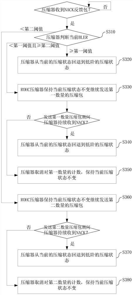
[0048]see image 3 , which is Embodiment 2 of the method for adjusting the compression state of the ROHC compressor provided in the present application, including the following steps.

[0049] Step S310: the same as step S110, where step S120, step S130, and step S160 are changed to step S320, step S330, and step S360, respectively.

[0050] Step S320: same as step S120.

[0051] Step S330: The ROHC compressor maintains the current compression state and continues to send the first number of compressed data packets to the ROHC decompressor. At this time, the current air interface quality is average, so the ROHC compressor delays the rollback of the compression state and continues to observe for a period of time.

[0052] Step S340: If the ROHC compressor continues to receive negative acknowledgment feedback packets from the ROHC decompressor during the period of sending the first number of compressed data packets, indicating that the current ROHC channel is no longer suitable...


PUM


Abstract

The invention discloses a compression state adjusting method of an ROHC compressor. The method includes that: step S110, when the ROHC compressor receives the feedback data packet of the NACK, the data block error rate BLER of the current air interface transmission channel is judged; when the BLER is larger than or equal to the first threshold value, the step S120 is executed; when the BLER is smaller than the first threshold value and the BLER is larger than or equal to the second threshold value, the step S130 is executed; when the BLER is smaller than the second threshold value, the step S160 is executed; S120, the ROHC compressor returns to the low-order compression state from the current compression state; S130, the ROHC compressor keeps the current compression state unchanged in thefirst time period and continues to send the compressed data packet to the ROHC decompressor, and the ROHC decompressor returns to the low-order compression state from the current compression state orkeeps the current compression state unchanged according to the situation; and step S160, wherein the step S160 is similar to the step S130 but is changed into a second time period. According to the ROHC compressor, the compression state adjustment of the ROHC compressor caused by transient deterioration of the air interface quality can be avoided.

Description

technical field [0001] The present application relates to an ROHC compression technology, in particular to a compression state adjustment method of an ROHC compressor. Background technique [0002] ROHC (Robust Header Compression, Robust Header Compression) is a technology for compressing the header of network data packets, which is mainly used in the air interface (air interface, also called air interface) of wireless transmission to improve the resource utilization. The functional entities of ROHC include a compressor and a decompressor. [0003] The ROHC protocol defines three working modes: Unidirectional mode, Bidirectional Optimistic mode, and Bidirectional Reliable mode. The one-way mode means that when the wireless link does not exist or the feedback channel cannot be used, the decompressor cannot send feedback information to the compressor. The two-way optimistic mode means that when there is an available feedback channel in the wireless link, the decompressor se...

Claims


Application Information

Patent Timeline
Patent Type & Authority Patents(China)
IPC IPC(8): H04L29/06H04L1/20H04L1/00
CPCH04L1/0001H04L1/203H04L69/04
Inventor 孙金重胡成松
Owner ASR SMART TECH CO LTD
Features
  • R&D
  • Intellectual Property
  • Life Sciences
  • Materials
  • Tech Scout
  • Unparalleled Data Quality
  • Higher Quality Content
  • 60% Fewer Hallucinations
Learn More