
High-efficiency pump and valve part processing and conveying equipment

A technology for parts processing and conveying equipment, which is applied in the field of high-efficiency pump and valve parts processing and conveying equipment, can solve the problems of low production efficiency of pump and valve parts, large demand for pump and valve parts, and easy contamination of conveying equipment, so as to reduce defective products The quantity, the effect of improving the conveying efficiency

Active Publication Date: 2020-05-05
ANHUI YINLONG PUMP VALVE
View PDF11 Cites 0 Cited by
  • Summary
  • Abstract
  • Description
  • Claims
  • Application Information

AI Technical Summary

Problems solved by technology

[0002] Pump and valve parts are indispensable parts in the use of pipelines. Pipelines are devices connected by pipes, pipe connectors and valves to transport gas, liquid or fluid with solid particles. The demand for pump and valve parts is large , during the processing of pump and valve parts, the pump and valve parts need to be transported, but in the process of transporting the pump and valve parts, the unqualified products in the pump and valve parts cannot be ground in time and transported to the next conveying equipment in time, The production efficiency of pump and valve parts will be reduced due to subsequent processing. During the conveying process, the conveying equipment is easy to get dirty. If it is not cleaned in time, it is easy to reduce the conveying efficiency of subsequent pump and valve parts.

Method used


Image

  • High-efficiency pump and valve part processing and conveying equipment
  • High-efficiency pump and valve part processing and conveying equipment
  • High-efficiency pump and valve part processing and conveying equipment

Examples


Embodiment Construction

[0021] The present invention will be further explained below in conjunction with the accompanying drawings and specific embodiments. It should be understood that the following specific embodiments are only used to illustrate the present invention and are not intended to limit the scope of the present invention. It should be noted that the words "front", "rear", "left", "right", "upper" and "lower" used in the following description refer to the directions in the drawings, and the words "inner" and "outer ” refer to directions towards or away from the geometric center of a particular part, respectively.

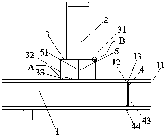
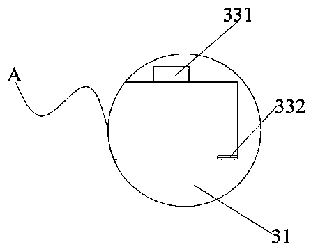
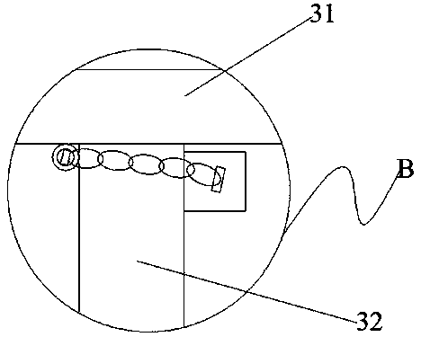
[0022] see Figure 1-5 , a high-efficiency pump and valve parts processing and conveying equipment, including a first conveying device 1 and a second conveying device 2, one side of the second conveying device 2 is located at the lower part of the first conveying device 1, and the second conveying device 2 is provided with maintenance The component 3 and the maintenance compon...


PUM


Abstract

The invention provides high-efficiency pump and valve part processing and conveying equipment which includes a first conveying device and a second conveying device. One side of the second conveying device is located at the lower part of the first conveying device, the first conveying device is started to placed machined pump valve parts into the first conveying device for conveying, staff puts thedefective pump valve parts into a fixed plate for subsequent processing, in the conveying process of the first conveying device, the pump valve parts in the fixed plate are ground, in the grinding process, a pushing device works and pushes the pump valve parts toward the two open sides of the fixed plate through a pushing plate, and grinding by the staff is facilitated; and after the grinding iscompleted, the pump valve parts after grinding are put into the second conveying device, after conveying by the first conveying device is completed, the water pump works, a through hole in a rotatingshaft enables a water source to flow into a drum, the external water source flows to the first conveying device through a through hole in the drum, and a brush horizontally moves and rotates to achieve the purpose of cleaning the first conveying device.

Description

technical field [0001] The invention belongs to a conveying device, in particular to a high-efficiency pump and valve part processing conveying device. Background technique [0002] Pump and valve parts are indispensable parts in the use of pipelines. Pipelines are devices connected by pipes, pipe connectors and valves to transport gas, liquid or fluid with solid particles. The demand for pump and valve parts is large , during the processing of pump and valve parts, the pump and valve parts need to be transported, but in the process of transporting the pump and valve parts, the unqualified products in the pump and valve parts cannot be ground in time and transported to the next conveying equipment in time, The production efficiency of the pump and valve parts will be reduced due to subsequent processing. During the conveying process, the conveying equipment is easy to get dirty. If it is not cleaned in time, it is easy to reduce the conveying efficiency of the subsequent pum...

Claims


Application Information

Patent Timeline
IPC IPC(8): B65G69/20
CPCB65G69/20
Inventor 吴翔吴辉吴杰
Owner ANHUI YINLONG PUMP VALVE
Learn More