A sand control screen for oil production

A base pipe and sand filter technology, which is applied in the direction of mining fluid, earthwork drilling, wellbore/well components, etc., can solve problems such as sand erosion, well wall deformation, screen pipe clogging, etc., to prevent sand migration and Clogging and erosion, reducing the effect of stress state changes

Active Publication Date: 2020-09-18
大庆市璞庆钻采设备制造有限公司
View PDF9 Cites 0 Cited by
  • Summary
  • Abstract
  • Description
  • Claims
  • Application Information

AI Technical Summary

Problems solved by technology

[0003] Sand control screens currently used include slotted screens, drilled screens, and wire-wrapped screens. During the use of slotted screens and drilled screens, well sand is prone to block the pipe seams or boreholes, and in In the process of use, mechanical expansion and gravel packing operations are required to ensure the positive support force on the well wall, which will easily lead to deformation of the well wall, resulting in the transfer of sand particles, resulting in screen blockage and erosion caused by sand particles , at the same time, the deformation of the borehole wall is likely to cause the position of the sand control screen to shift
[0004] When the current sand control screen is in use, the holes at the openings of the base pipe are all linear holes, so that the pressure inside and outside the base pipe is consistent, so that the pressure of oil entering the inside of the base pipe is completely provided by the pressure in the well, and the base pipe The pressure on the inside and outside is the same, which causes the flow rate of the oil to be consistent with the flow rate of the sand particles, which can easily cause the sand particles to block the screen holes

Method used


Image

  • A sand control screen for oil production
  • A sand control screen for oil production
  • A sand control screen for oil production

Examples


Embodiment Construction

[0021] The following will clearly and completely describe the technical solutions in the embodiments of the present invention with reference to the accompanying drawings in the embodiments of the present invention. Obviously, the described embodiments are only some, not all, embodiments of the present invention. Based on the embodiments of the present invention, all other embodiments obtained by persons of ordinary skill in the art without making creative efforts belong to the protection scope of the present invention. The drawings in the embodiments of the present invention: the different types of section lines in the drawings are not marked according to the national standard, and there is no requirement for the material of the components, but to distinguish the cross-sectional views of the components in the drawings.

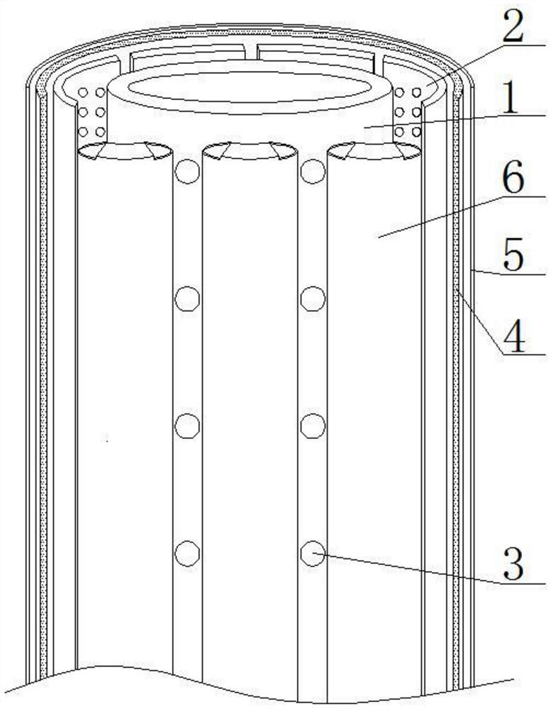
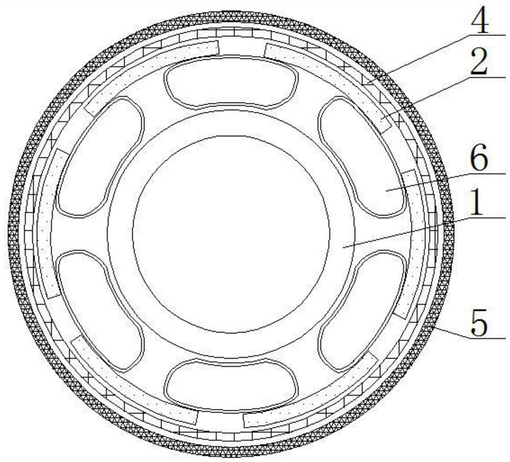
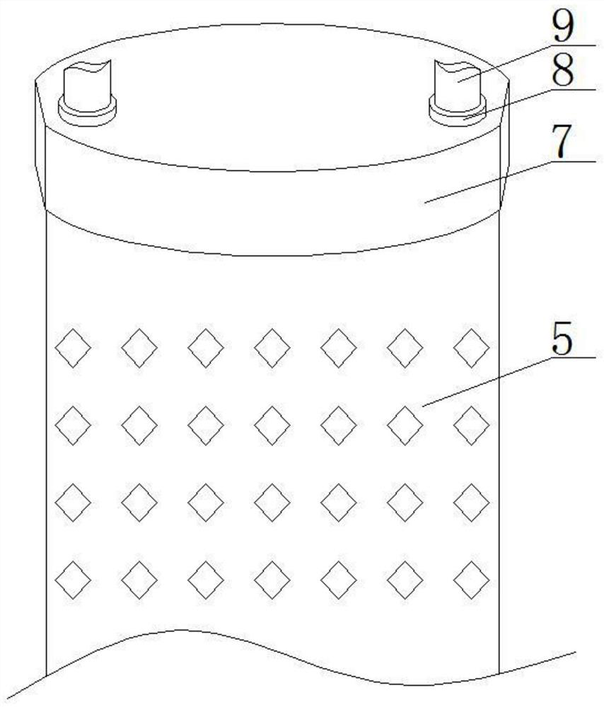
[0022] see Figure 1-5 , a sand control screen for oil production, comprising an internal base pipe 1, a filter device 3 is installed on the front of the inte...


PUM


Abstract

The invention relates to the technical field of oil exploitation and discloses a sand prevention sieve tube for oil production. The sand prevention sieve tube comprises an inner base tube, wherein special-shaped expansion tubes are placed on the outer surface of the inner base tube in a contacting manner, drainage plates are placed on the outer surfaces of the special-shaped expansion tubes in a contacting manner, the outer surfaces of the drainage plates are movably covered with a sand filtering net tube, the outer surface of the sand filtering net tube is movably covered with an outer protective shield, a packer is fixed and clamped at the top of the outer protective shield, and communicating seats are fixed and clamped at the top of the packer. According to the sand prevention sieve tube for oil production, through matching of the special-shaped expansion tubes arranged on the outer side of the inner base tube, the packer and hydraulic tubes, pressure is applied to the wall of the sand prevention sieve tube, so that the wall of the sieve tube deforms according to the wall of the wall of a well, the wall of the sieve tube can be rapidly, safely and reliably attached to the wall of the well, deformation of the wall of the well when the sand prevention sieve tube is fixed through mechanical expansion and gravel packing is further prevented, stress state change is reduced, sandmigration is prevented, and sieve blocking and erosion are prevented.

Description

technical field [0001] The invention relates to the technical field of oil extraction equipment, in particular to a sand control screen for oil extraction. Background technique [0002] During the production of oil and gas wells, the formation of sand is ubiquitous. Taking sand control measures is the main means to solve the problem of sand production in oil and gas wells. Sand control screens are the most important and widely used tools in sand control measures. The main function of oil screens is For sand control, the different geological environments of oil wells lead to different steel grades and types of screens used. [0003] Sand control screens currently used include slotted screens, drilled screens, and wire-wrapped screens. During the use of slotted screens and drilled screens, well sand is prone to block the pipe seam or borehole, and in In the process of use, mechanical expansion and gravel packing operations are required to ensure the positive support force on ...

Claims


Application Information

Patent Timeline
Patent Type & Authority Patents(China)
IPC IPC(8): E21B43/08E21B43/10
CPCE21B43/08E21B43/084E21B43/086E21B43/105
Inventor 王成军
Owner 大庆市璞庆钻采设备制造有限公司
Why Eureka
Try Eureka