Short-cut yarn material raising type drying device

A drying device and chopped yarn technology, applied in the directions of drying, dryer, drying gas arrangement, etc., can solve the problems of inability to air-dry chopped strands, difficult to collect, and chopped strands are easy to float everywhere, etc., and achieve high efficiency , good drying effect

Inactive Publication Date: 2020-05-05
五河县维佳复合材料有限公司
View PDF6 Cites 4 Cited by
  • Summary
  • Abstract
  • Description
  • Claims
  • Application Information

AI Technical Summary

Problems solved by technology

[0002] Chopped yarn, as the name suggests, is to cut glass fiber yarn or long fiber into short required lengths. In the production process of chopped yarn, firstly, the yarn or long fiber needs to be pickled to remove impurities on the surface, and then Cutting, drying and other pr

Method used


Image

  • Short-cut yarn material raising type drying device
  • Short-cut yarn material raising type drying device
  • Short-cut yarn material raising type drying device

Examples


Example Embodiment

[0022] Example 1

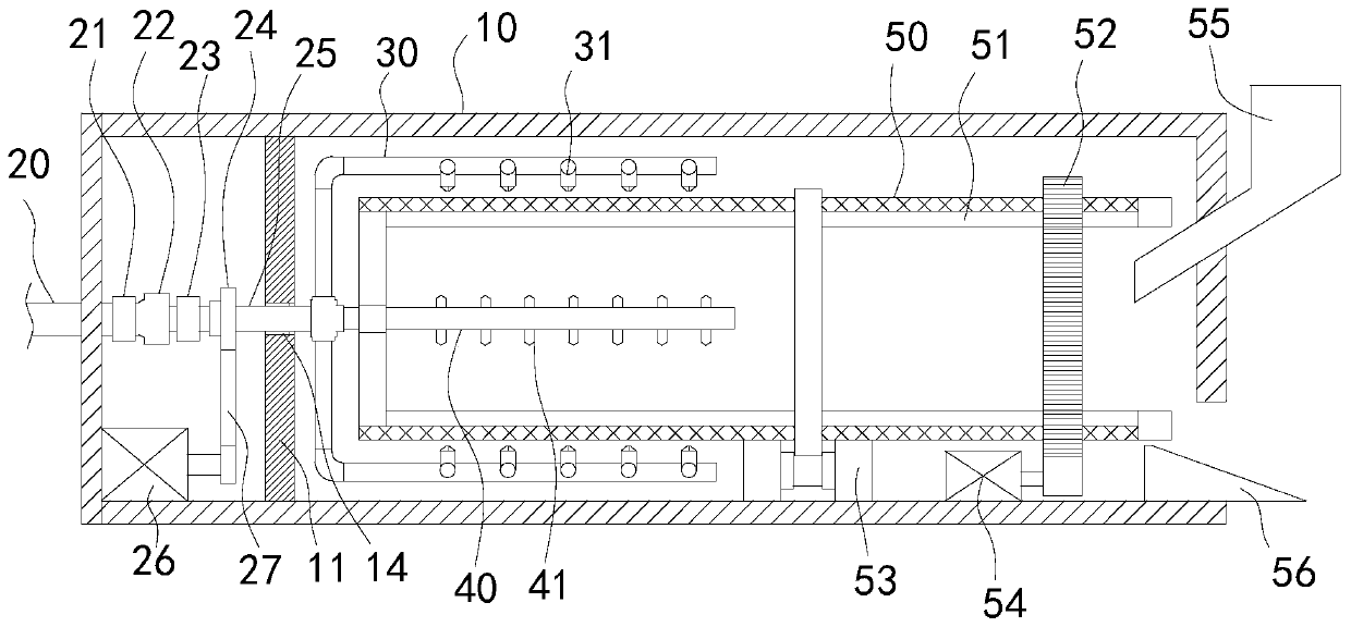
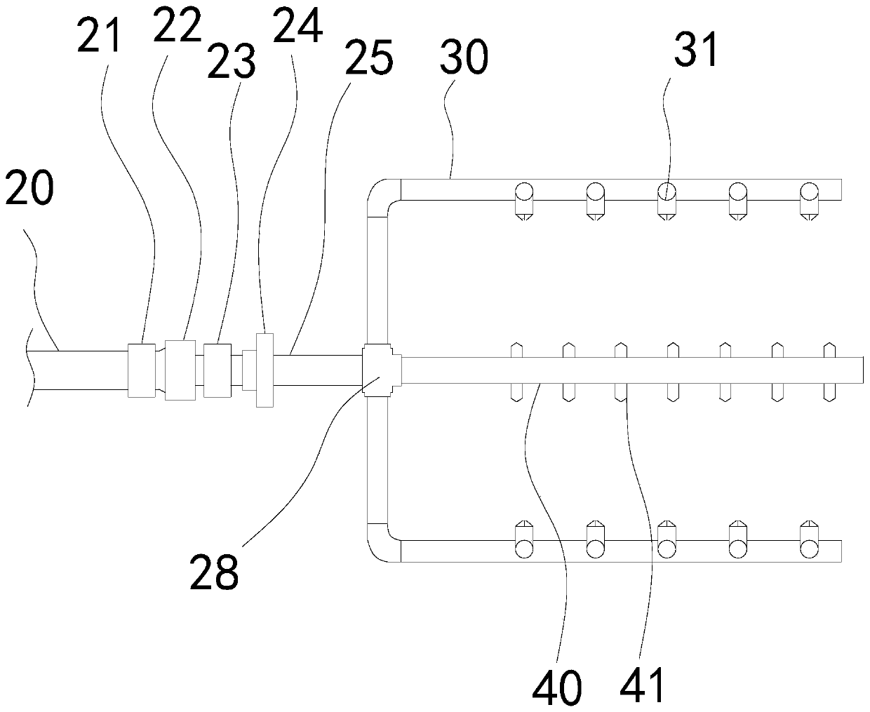
[0023] Such as figure 1 , figure 2 As shown, the present invention provides a chopped yarn raising type drying device, including:

[0024] The housing 10 is provided with a partition 11 inside the left side of the housing 10, and a discharge port is provided at the bottom of the right side of the housing 10;

[0025] The feeding device is arranged in the housing 10 and located on the right side of the partition 11, wherein the feeding device includes a rotating drum 50, and the left side of the rotating drum 50 is sealed , The left end of the drum 50 can be sealed with a sealing plate, and the right side of the drum 50 can be provided with an opening to facilitate feeding. For better feeding and discharging, a feeding pipe 55 is provided above the opening. The bottom end of the opening can extend into the inside of the drum 50, the opening bottom is provided with a discharge plate 56, and the discharge plate 56 can be a sloping plate body, when the dried chopped ...

Example Embodiment

[0031] Example 2

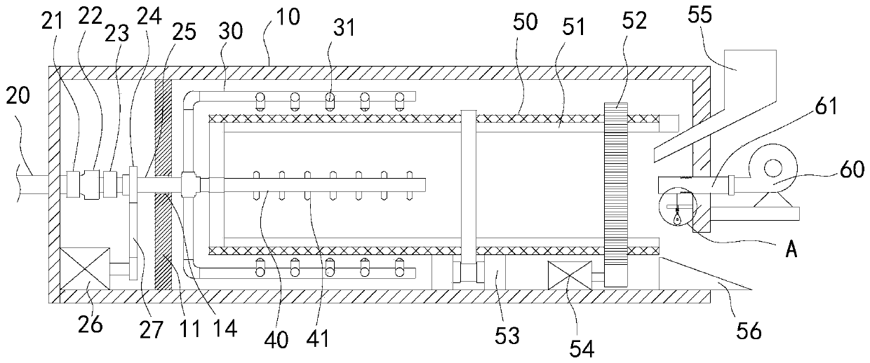
[0032] Such as figure 1 , figure 2 As shown, the present invention provides a chopped yarn raising type drying device, including:

[0033] The housing 10 is provided with a partition 11 inside the left side of the housing 10, and a discharge port is provided at the bottom of the right side of the housing 10;

[0034] The feeding device is arranged in the housing 10 and located on the right side of the partition 11, wherein the feeding device includes a rotating drum 50, and the left side of the rotating drum 50 is sealed , The left end of the drum 50 can be sealed with a sealing plate, and the right side of the drum 50 can be provided with an opening to facilitate feeding. For better feeding and discharging, a feeding pipe 55 is provided above the opening. The bottom end of the opening can extend into the inside of the drum 50, the opening bottom is provided with a discharge plate 56, and the discharge plate 56 can be a sloping plate body, when the dried chopped ...


PUM


Abstract

The invention discloses a short-cut yarn material raising type drying device. The short-cut yarn material raising type drying device comprises a shell, a feeding device and a drying mechanism, whereina partition plate is arranged in the left side of the shell, and the bottom of the right side of the shell is provided with a discharging port; the feeding device is arranged in the shell and locatedon the right side of the partition plate; the feeding device comprises a rotating drum; the left side of the rotating drum is sealed, and the right side of the rotating drum is provided with an opening; a feeding pipe is arranged above the opening, and a discharging plate is arranged at the bottom of the opening; and the drying mechanism is arranged on the left side of the shell. The rotating drum in the short-cut yarn material raising type drying device is in a relatively sealed environment all the time, and when short-cut yarn in the rotating drum is dried, a dry environment in the shell can be maintained; and due to rotating of the rotating drum and air blowing of the drying mechanism, the short-cut yarn in the rotating drum can be raised, the drying effect is good, and efficiency is high.

Description

Technical field: [0001] The invention relates to the field of glass fiber production, in particular to a chopped yarn lifting type drying device. Background technique: [0002] Chopped yarn, as the name suggests, is to cut glass fiber yarn or long fiber into short required lengths. In the production process of chopped yarn, firstly, the yarn or long fiber needs to be pickled to remove impurities on the surface, and then Cutting, drying and other processes, the chopped yarn needs to be dried after cutting. When the chopped yarn is dried, because of its light weight, it is usually dried with hot air, which makes the chopped yarn easy to float around and difficult to collect. , and the fan cannot effectively dry the chopped yarn. Invention content: [0003] The technical problem to be solved by the present invention is to provide a chopped yarn lifting type drying device with good drying effect. [0004] Technical problem to be solved by the present invention adopts followi...

Claims


Application Information

Patent Timeline
IPC IPC(8): F26B11/04F26B21/00F26B25/00
CPCF26B11/04F26B21/00F26B25/008
Inventor 卢克香
Owner 五河县维佳复合材料有限公司
Why Eureka
Try Eureka