

Body drying device
A drying body and one side technology, applied in the field of drying equipment, can solve the problems of weakened gas flow rate and poor drying effect, and achieve the effect of increasing the drying surface, improving efficiency, and uniform drying speed
- Summary
- Abstract
- Description
- Claims
- Application Information
AI Technical Summary
Problems solved by technology
Method used
Image

Examples
Embodiment 1
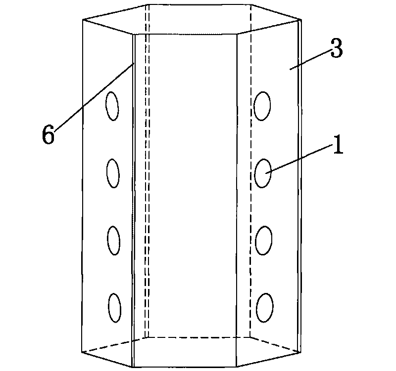
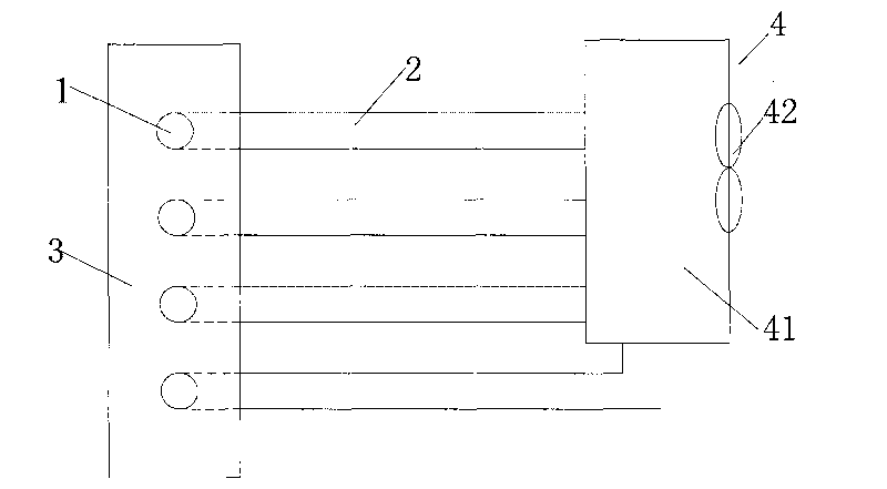
[0051] like figure 1 and figure 2 In the shown embodiment one, the body drying device in this embodiment is a hexagonal prism cabinet structure, wherein the five sides of the hexagonal prism cabinet structure are surrounded by five side walls 3, and one side serves as the user Access door. Four circular tubular blowing outlets 1 arranged from top to bottom are arranged on the alternate side walls 3, and a strip-shaped exhaust port is provided from top to bottom at the junction of the alternate side walls 3 6. The sum of the areas of the three air outlets is equal to three times the sum of the areas of all the air outlets 1 . figure 2 Shown in is a structural schematic diagram of the air supply system suitable for the body drying device of the present invention. It can be seen that each of the blowing outlets 1 is connected to the air supply pipe 2 that is independently connected to the drying gas supply source 4 The air outlet 1 is an air outlet structure in which the air...
Embodiment 2
[0056] like image 3 In the second embodiment shown, the structure of the body drying device in this embodiment is basically the same as that in the first embodiment, and only the structure of the air outlet 1 described in the first embodiment is changed. In this embodiment, the air outlet 1 is tubular and rectangular, and the long side is placed along the horizontal direction, and the length in the horizontal direction is slightly smaller than the average width of the user (about 40cm), such as image 3 As shown, the side wall 3 is provided with a longitudinal sectional view of the position of the blowing port 1. In this view, only part of the blowing port is shown. It can be seen that the upper and lower sides of the part of the blowing port 1 passing through the side wall 3 have circles Arc-shaped protrusions, and the position where the side wall meets the protrusions is provided with a groove that matches the shape of the arc-shaped protrusions. The grooves are engaged wit...
Embodiment 3
[0062] like Figure 4 As shown, the body drying device in this embodiment is basically the same as that in Embodiment 2, only the arrangement of the air outlet in Embodiment 2 is changed. In this embodiment, two vertically swinging blowing ports 1a and one horizontally swinging blowing port 1b are arranged on each side wall 3 provided with blowing ports 1, and are arranged alternately. Through such a design, it can be ensured that the blown air can not only meet the purpose of adjusting the air outlet direction according to the height of the human body, but also meet the purpose of adjusting the air outlet direction according to the width of the human body. In addition, the gas flow velocity of the air outlet 1 in the first embodiment is changed, and the gas flow velocity of the air outlet 1 in this embodiment is 20 m / s.
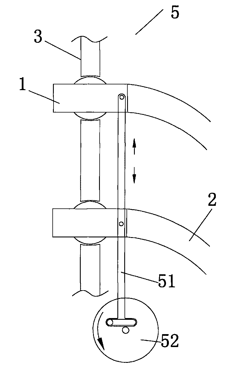
[0063] like Figure 5 As shown, the structure of the tuyere 1 in the second or third embodiment can be replaced by Figure 5 structure shown. The blowin...
PUM
 Abstract
Description
Claims
Application Information