A thermal protection installation structure of a pressure sensor in a narrow space

A pressure sensor and installation structure technology, which is applied to the testing of machines/structural components, measuring devices, instruments, etc., can solve problems such as inaccurate measurement of pressure sensors, harsh measurement environments, and limited installation space, and achieve good thermal stability. Protective effect, extend the heat transfer path, and improve the effect of anti-vibration ability

Active Publication Date: 2021-11-02
XIAN AEROSPACE PROPULSION INST
View PDF0 Cites 0 Cited by
  • Summary
  • Abstract
  • Description
  • Claims
  • Application Information

AI Technical Summary

Problems solved by technology

[0003] The main purpose of the present invention is to solve the technical problem that the pressure sensor is prone to inaccurate measurement or even measurement failure due to the limited installation space and harsh measurement environment in the prior art when the pressure sensor is used to measure the chamber pressure of the combustion chamber. Thermal protection installation structure of pressure sensor in narrow space

Method used


Image

  • A thermal protection installation structure of a pressure sensor in a narrow space
  • A thermal protection installation structure of a pressure sensor in a narrow space
  • A thermal protection installation structure of a pressure sensor in a narrow space

Examples


Embodiment Construction

[0033] The following Examples and drawings of the present invention, the technical solutions of the present invention are clearly and completely described, obviously, not to limit the described embodiment of the present invention.

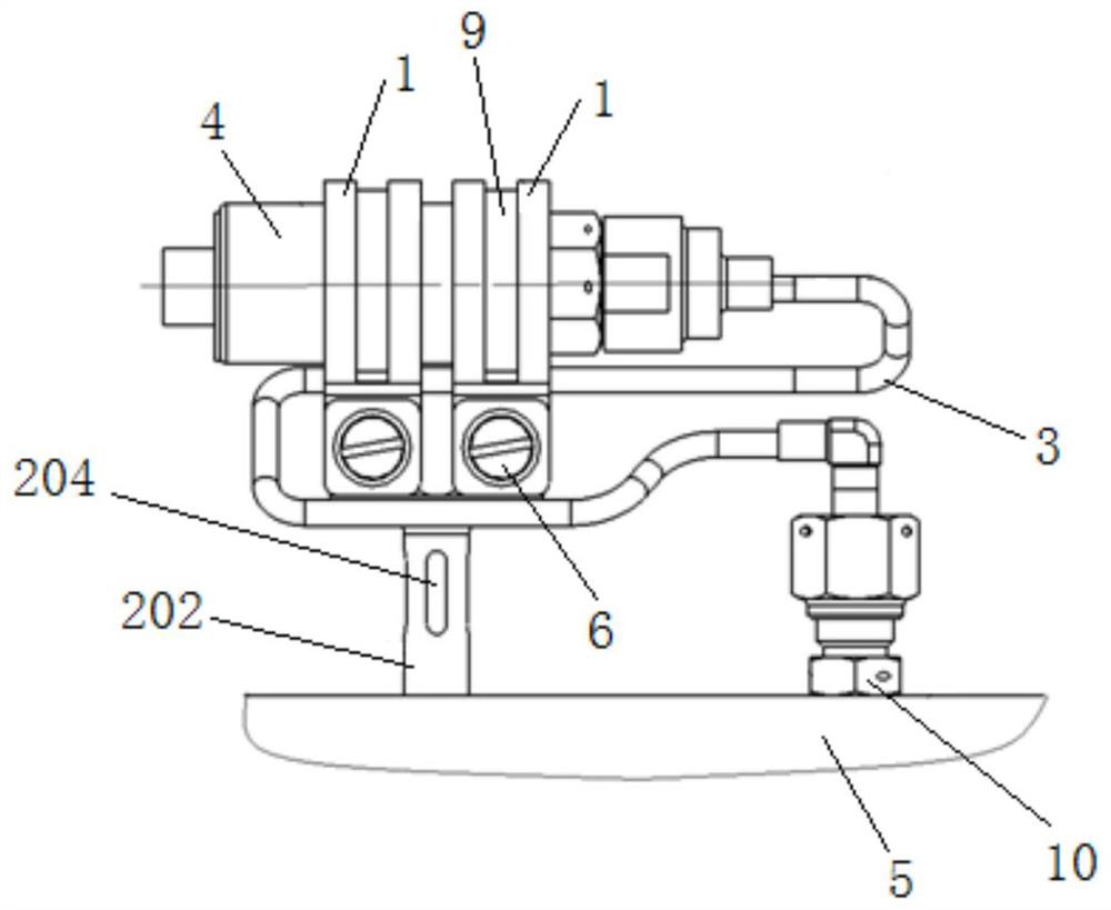
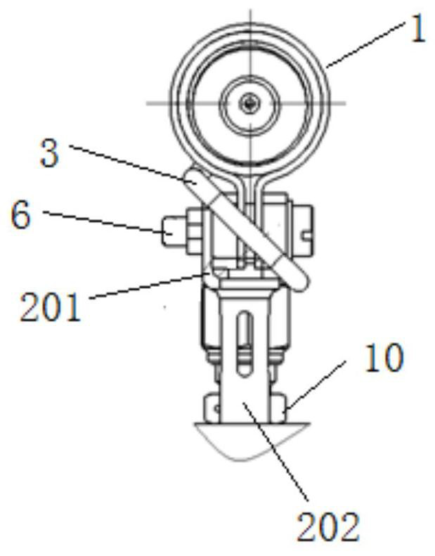
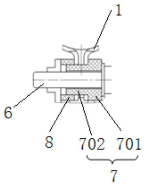
[0034] like Figures 1 to 7 A load cell narrow space heat shield mounting structure comprising a support base 2, pressure conduit 3 and two clamp 1. like Figure 4 with Figure 5 , The upper supporting base 2 is L-shaped fixing plate 201 for fixing the clamp 1, the lower part of the support base 202, support base 202 connected to the bottom end of the fixing plate 201, and the other end fixed to the wall surface of the combustion chamber 5, play a role in supporting and fixing. The clamp 1 may be the number of a plurality or greater than two, if a stability of the mounting structure may be reduced, by increasing the width of the clamp can be used as make up 1; 1 may be a plurality of clamp, fixing the support more reliable. Number and form a clamp can be ...


PUM


Abstract

The invention belongs to the installation structure of a high-temperature gas pressure measuring sensor. In order to solve the problem that in the prior art, when the pressure measuring sensor is used to measure the chamber pressure of the combustion chamber, due to the limited installation space and the harsh measurement environment, the pressure measuring sensor is prone to inaccurate measurement or even measurement failure. The technical problem is to provide a heat protection installation structure for a pressure sensor in a narrow space, including a support base, a pressure measurement conduit and a clamp; the upper part of the support base is an L-shaped fixing plate, and the lower part is a supporting base; one end of the supporting base is connected to the fixing plate The bottom and the other end are fixed on the wall of the combustion chamber; the clamp is set on the outside of the pressure sensor, and the clamp joint is installed on the side wall of the fixed plate; one end of the pressure measurement conduit is connected to the detection end of the pressure sensor , the other end communicates with the interior of the combustion chamber, the middle part of the pressure measurement conduit is coiled, and the pressure measurement conduit bypasses the support seat.

Description

Technical field [0001] The present invention is in the hot-gas pressure measuring sensor mounting structure, in particular to a load cell narrow space heat shield mounting structure. Background technique [0002] Combustion chamber pressure is one of the key parameters of the engine telemetry, whether by measuring this parameter reflects the normal engine operation. The overall structure of the engine and the measurement layout requirements, required chamber pressure measuring point in the selected portion of the combustion chamber body, and a load sensor disposed near the inner cowl required. Due to the large inner cowl equipment, pressure sensors available space is very limited, and the harsh environment in which the combustion chamber body portion of the housing wall temperature of not lower than 700 deg.] C, an internal combustion gas stream temperatures not lower than 800 deg.] C, the vibration housing middleweight, long working hours. If the conventional fixed support means...

Claims


Application Information

Patent Timeline
Patent Type & Authority Patents(China)
IPC IPC(8): G01M15/02F16M11/04
CPCF16M11/04G01M15/02
Inventor 黄鋆樊根民金莉戴进梁俊龙李光熙石波
Owner XIAN AEROSPACE PROPULSION INST
Why Eureka
Try Eureka