A spectacle lens with annular cylindrical microstructure on the surface

A technology of microstructure and spectacle lens, which is applied in glasses/protective glasses, glasses/goggles, instruments, etc., and can solve the problems that the processing technology has not yet been established.

Active Publication Date: 2020-12-11
温州视顺科技有限公司
View PDF2 Cites 1 Cited by
  • Summary
  • Abstract
  • Description
  • Claims
  • Application Information

AI Technical Summary

Problems solved by technology

At present, this design method has not yet been carried out in the field of lens design, and the processing technology has not yet been established.

Method used


Image

  • A spectacle lens with annular cylindrical microstructure on the surface
  • A spectacle lens with annular cylindrical microstructure on the surface
  • A spectacle lens with annular cylindrical microstructure on the surface

Examples


Embodiment Construction

[0022] The following Examples with reference to specific embodiments of the present invention is further described, embodiments of the present invention is to enable those skilled in the art to better understand the present invention without any limitation of the present invention.

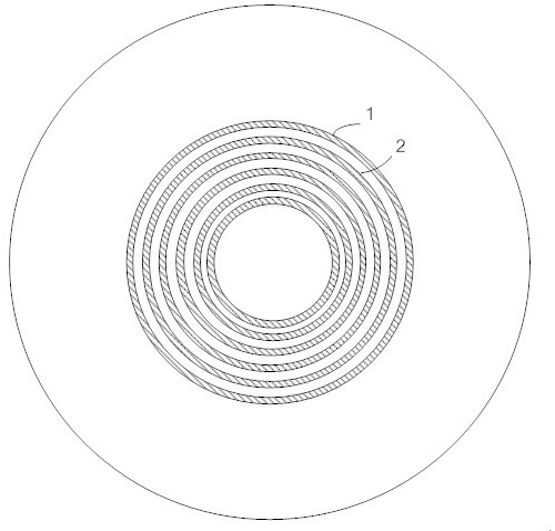
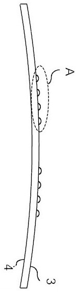
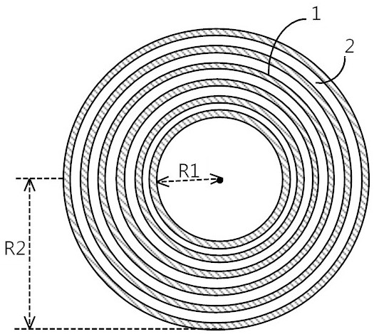
[0023] figure 1 The surface is a plan view of the embodiment of the present invention is an ophthalmic lens having a cylindrical annulus microstructures. When the front surface of the lens (i.e., convex) surface of a cylindrical annulus located microstructure, figure 2 Yes figure 1 Sectional view of the lens of FIG. image 3 Yes figure 1 Partially enlarged plane of the lens shown in FIG. Figure 4 Yes figure 2 A cross-sectional enlarged view of the region shown in FIG. Figure 5 Is possible when viewed in the outer cylindrical surface microstructure was distributed through the pupil region annulus 4mm embodiment of the present invention is a plan view showing the lens. BRIEF DESCRIPTION surface accordin...


PUM


Abstract

An ophthalmic lens with annular cylindrical microstructures on the surface, within a specific aperture range of the lens, a plurality of annular cylindrical microstructures with different radii take the geometric center of the lens as the center, and are regularly nested and arranged to form a radial array , each annular cylindrical microstructure can produce relatively stable refractive power and higher-order aberrations. The spectacle lens of the present invention has an excellent and stable visual correction effect outside the microstructure distribution area of ​​the annulus cylinder; in the distribution area of ​​the microstructure of the annulus cylinder used for side-viewing, a diameter is introduced for the spectacle-wearing eye. In terms of visual effects, regular astigmatism and irregular astigmatism in the peripheral field of view coexist, and low-order and high-order disturbances of the incident wave surface in the peripheral field of view of the human eye are realized, so that the imaging of the peripheral field of view of the lens decline in quality. The lens is mainly suitable for adolescents with rapid myopia development or hyperopia and defocus around the retina. It can introduce high-order aberrations and myopia defocus along the radial meridian in the peripheral retinal visual field.

Description

Technical field [0001] The present invention particularly relates to the design and process technology field of optical lenses, in particular to a spectacle lens having a surface microstructure cylindrical annulus. Background technique [0002] Peripheral retinal defocus phenomenon refers to the human eye refractive refractive errors occurring in the system at the periphery of the retina, and there is often myopic retinal peripheral hyperopic defocus, and vice versa, the peripheral myopic patients hyperopia retinal defocus exists. Clinical studies have found that peripheral hyperopic retinal defocus is a key factor in promoting the development of myopia. Currently, from Jiaozuo surrounding the lens with the introduction on the market are mainly two. One is the increase in the peripheral region of the microlens array side of the lens. This interference microlens refractive power of the lens, thereby changing the refractive structure of the lens periphery, the periphery of the orig...

Claims


Application Information

Patent Timeline
Patent Type & Authority Patents(China)
IPC IPC(8): G02C7/06G02C7/02
CPCG02C7/06G02C7/02G02C2202/24G02C7/022
Inventor 厉以宇陈娇洁陈浩瞿佳
Owner 温州视顺科技有限公司
Why Eureka
Try Eureka