
Environment-friendly cable dehumidifying and drying equipment

A technology for drying equipment and cables, used in cable/conductor manufacturing, circuits, electrical components, etc., can solve the problems of not saving labor, affecting the rotation of the fan blades, and having a lot of dust on the fan blades, achieving efficient, fast drying and dehumidification, and strong energy saving. Effect

Active Publication Date: 2020-05-05
孟正明
View PDF10 Cites 1 Cited by
  • Summary
  • Abstract
  • Description
  • Claims
  • Application Information

AI Technical Summary

Problems solved by technology

[0002] At present, the traditional cable dehumidification and drying equipment on the market is not easy to move on the horizontal plane. When moving, the cable dehumidification and drying equipment needs to be manually carried and is relatively stressful, which cannot save labor. The traditional cable dehumidification and drying equipment is not easy to clean the dust accumulated on the fan blades. Long-term use of the fan blades accumulates a lot of dust, which affects the rotation of the fan blades, thereby reducing work efficiency
[0003] In the Chinese utility model patent document with the publication number CN207651256U, an environmentally friendly cable dehumidification and drying equipment is disclosed. When the dehumidification and drying equipment needs to be moved, the switch is turned on, and the KS02Y controller controls the hydraulic pump to change the pressure in the hydraulic cylinder. The air pressure pushes the telescopic rod to extend downward, pushes out the push plate, thereby lifting the cable dehumidification and drying equipment, and then pushes the cable dehumidification and drying equipment to move on the horizontal plane. When it moves to an appropriate position, the KS02Y controller controls the hydraulic pump to change the hydraulic cylinder The air pressure inside makes the telescopic rod store the push plate inside the base. After the cable dehumidification and drying equipment has been used for a period of time, open the top cover, and rotate the rotating buckle installed on the connecting rod to rotate and separate the rotating buckle from the mounting base, thereby connecting The fan blades fixed on one side of the rod are disassembled from one end of the rotating shaft, which is convenient for cleaning the fan blades, but the air is completely relied on to dry the cables, which is slow and affects work efficiency

Method used


Image

  • Environment-friendly cable dehumidifying and drying equipment
  • Environment-friendly cable dehumidifying and drying equipment
  • Environment-friendly cable dehumidifying and drying equipment

Examples


Embodiment 1

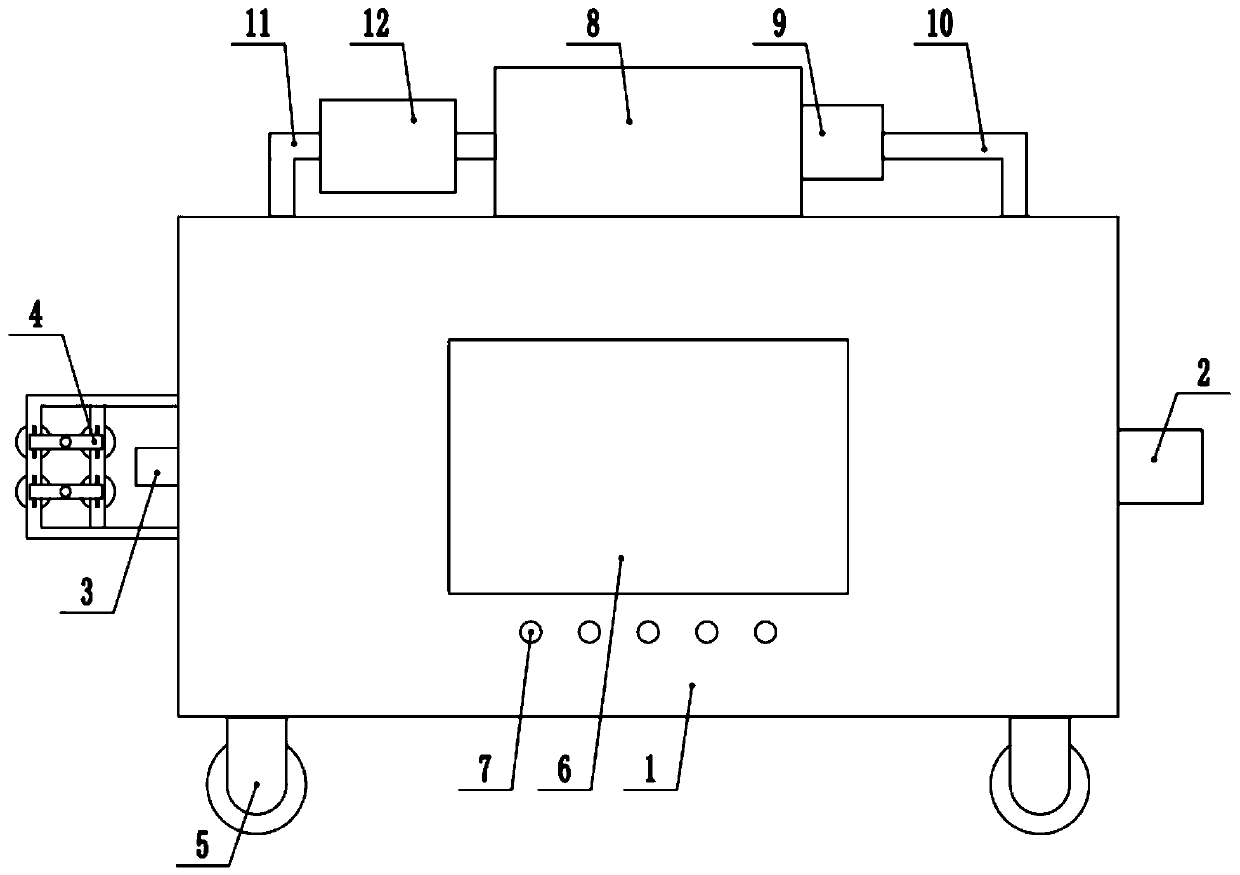
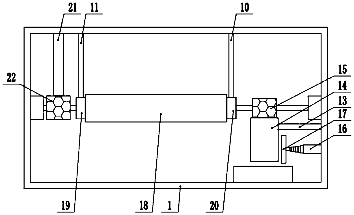
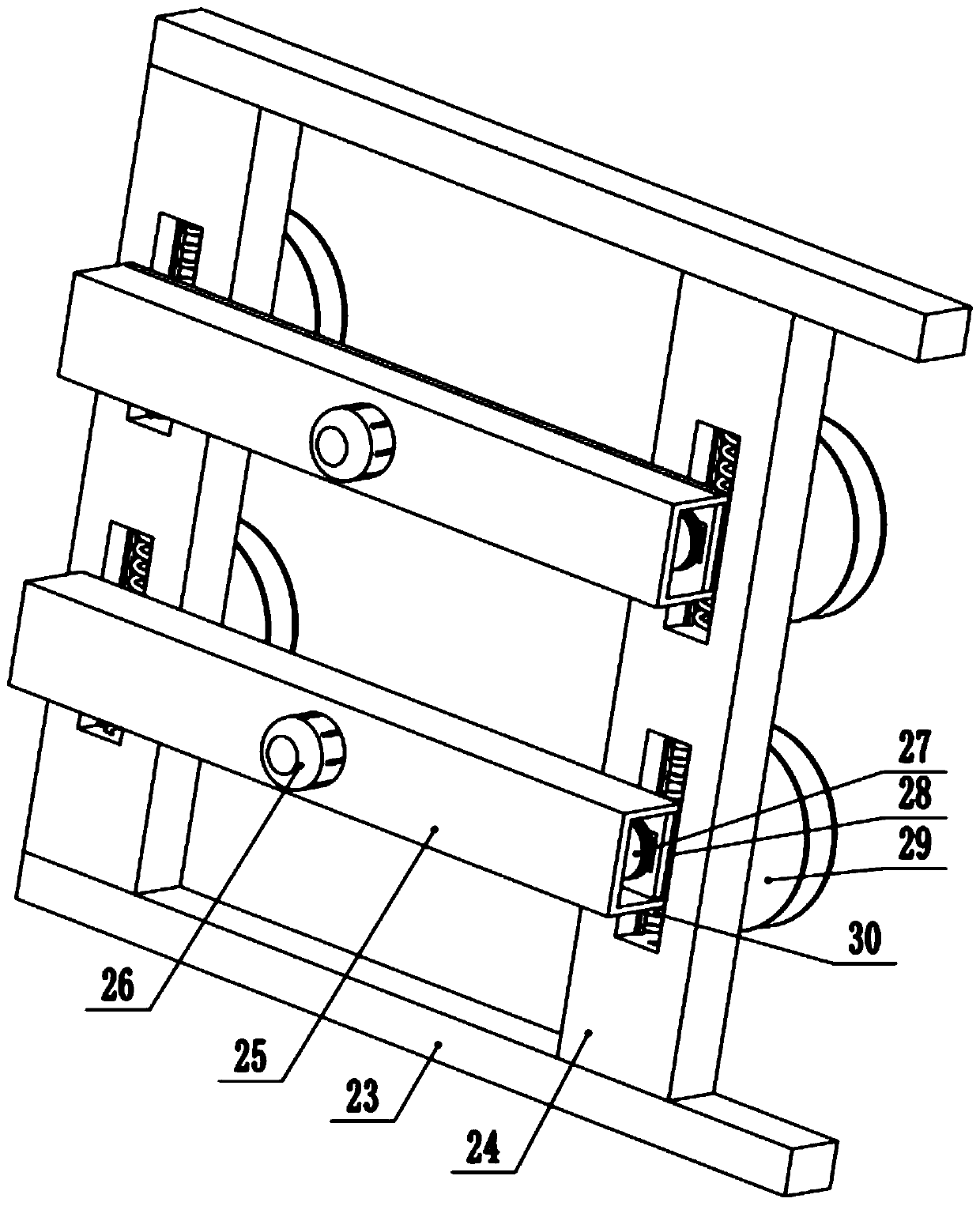
[0025] see Figure 1-3 , an environment-friendly cable dehumidification and drying equipment, including a dehumidification box 1, one end of the dehumidification box 1 is fixed with a conveying device 4, and the dehumidification box 1 is provided with a drying and dehumidification mechanism, and the drying and dehumidification mechanism includes a The hot air cover 18 in the middle part of the dehumidification box 1, the two ends of the hot air cover 18 are respectively fixedly connected to the air inlet cover 19 and the return air cover 20, and the tops of the air inlet cover 19 and the return air cover 20 are respectively fixedly connected to the exhaust pipe 11 and the return air Pipe 10, the top of the dehumidification box 1 is fixedly connected to the drying box 8, one end of the drying box 8 is fixedly connected to the blower 9, the input end of the blower 9 is fixedly connected to the return air pipe 10, and the exhaust pipe 11 passes through the dehumidification box 1 ...

Embodiment 2

[0029] see Figure 1-3 , including a dehumidification box 1, one end outside the dehumidification box 1 is fixedly provided with a conveying device 4, and a dry dehumidification mechanism is arranged inside the dehumidification box 1, and the dry dehumidification mechanism includes a hot air jacket 18 arranged in the middle of the dehumidification box 1 , the two ends of the hot air cover 18 are respectively fixedly connected to the air inlet cover 19 and the return air cover 20, and the tops of the air inlet cover 19 and the return air cover 20 are respectively fixedly connected to the exhaust pipe 11 and the return air pipe 10, the dehumidification box 1 The top is fixedly connected to the drying box 8, one end of the drying box 8 is fixedly connected to the blower 9, the input end of the blower 9 is fixedly connected to the return air pipe 10, and the exhaust pipe 11 passes through the dehumidification box 1 and is fixedly connected to the drying box 8. The exhaust pipe 11 ...


PUM


Abstract

The invention discloses environment-friendly cable dehumidifying and drying equipment. The invention relates to the technical field of cable equipment. The equipment comprises a dehumidification box.A conveying device is fixedly arranged at one end outside the dehumidifying box. A drying and dehumidifying mechanism is arranged in the dehumidifying box. The drying and dehumidifying mechanism comprises a hot air sleeve arranged in the middle of the interior of the dehumidification box. Two ends of the hot air sleeve are fixedly connected with an air inlet cover and an air return cover respectively. The top ends of the air inlet cover and the air return cover are fixedly connected with an exhaust pipe and an air return pipe respectively. The top end of the dehumidification box is fixedly connected with a drying box. One end of the drying box is fixedly connected with a blower. The input end of the blower is fixedly connected with the return air pipe. According to the invention, by arranging the drying and dehumidifying mechanism, water absorption and hot air drying can be conducted on a cable, so that efficient and rapid drying and dehumidifying can be conducted on the cable; dried humid and hot air can be dried and recycled; and the energy saving performance is high.

Description

technical field [0001] The invention relates to the technical field of cable equipment, in particular to an environment-friendly cable dehumidification and drying equipment. Background technique [0002] At present, the traditional cable dehumidification and drying equipment on the market is not easy to move on the horizontal plane. When moving, the cable dehumidification and drying equipment needs to be manually carried and is relatively stressful, which cannot save labor. The traditional cable dehumidification and drying equipment is not easy to clean the dust accumulated on the fan blades. Long-term use of the fan blades accumulates a lot of dust, which affects the rotation of the fan blades, thereby reducing work efficiency. [0003] In the Chinese utility model patent document with the publication number CN207651256U, an environmentally friendly cable dehumidification and drying equipment is disclosed. When the dehumidification and drying equipment needs to be moved, th...

Claims


Application Information

Patent Timeline
IPC IPC(8): H01B13/30
CPCH01B13/30
Inventor 孟正明郑元态
Owner 孟正明
Learn More