
Infusion stopping clip device for indwelling needle

A liquid stop clip and indwelling needle technology, applied in the direction of needles, instruments introduced into the body, valves, etc., can solve the problems of thrombosis, human injury, clogging of the cannula, etc., and achieve the effect of preventing blood backflow

Pending Publication Date: 2020-05-08
JIANGXI FENGLIN MEDICAL APPLIANCE +2
View PDF0 Cites 0 Cited by
  • Summary
  • Abstract
  • Description
  • Claims
  • Application Information

AI Technical Summary

Problems solved by technology

[0003] During the indwelling needle, the liquid flow channel must be blocked with a liquid stop clip. After closing the liquid stop clip, it is easy to cause negative pressure in the catheter during the non-infusion process. Even a slight negative pressure will cause blood to flow into the indwelling catheter. In the cannula of the needle, a thrombus will quickly form and block the cannula, causing harm to the human body
For this reason, in recent years, there have been many products of elastic hemostatic clips or positive pressure hemostatic clips, which have a positive effect on preventing blood backflow from forming thrombus. In the residual liquid of the tube, when a certain concentration is reached, a thrombus will be formed to block the tube
[0004] Therefore, when suspending the infusion treatment for indwelling, it is necessary to lock the tube with anticoagulant heparin, or flush the tube with normal saline, and repeat the flushing every 6 to 8 hours. However, this will increase the nursing workload, increase the chance of infection and increase the Medical expenses

Method used


Image

  • Infusion stopping clip device for indwelling needle
  • Infusion stopping clip device for indwelling needle
  • Infusion stopping clip device for indwelling needle

Examples


Embodiment Construction

[0026] In order to make the purpose, features and advantages of the present invention more obvious and understandable, the specific implementation manners of the present invention will be described in detail below in conjunction with the accompanying drawings. Several embodiments of the invention are shown in the drawings. However, the present invention can be embodied in many different forms and is not limited to the embodiments described herein. Rather, these embodiments are provided so that the disclosure of the present invention will be thorough and complete.

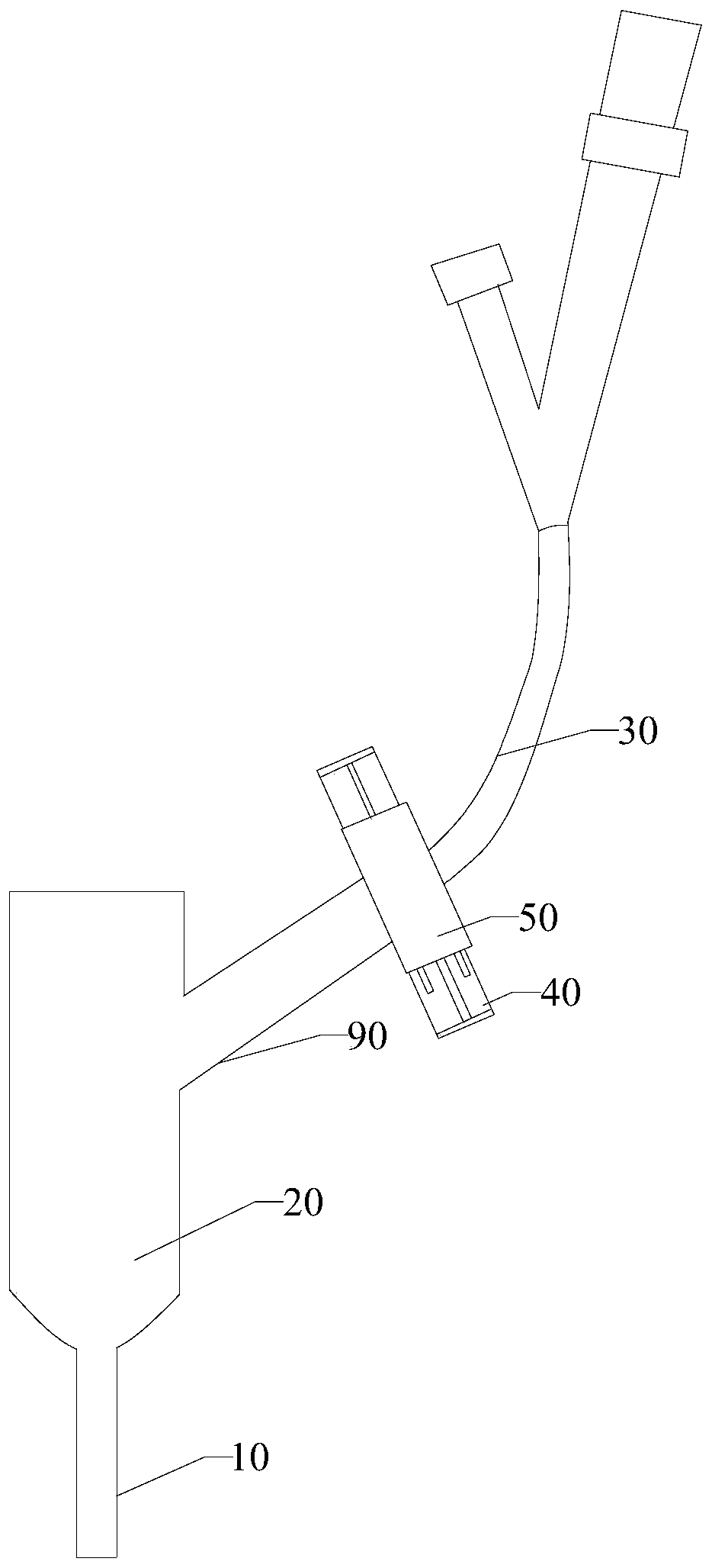
[0027] Please refer to figure 1 As shown, the embodiment of the present invention provides an intravenous indwelling needle, including a cannula 10, an extension tube 30 and an indwelling needle liquid-stop clip device. The side wall is connected with an extension tube 30, and the extension tube 30 is used to flow the medicinal liquid into the catheter adapter 20, and then enter the patient's venous blood vessel f...


PUM


Abstract

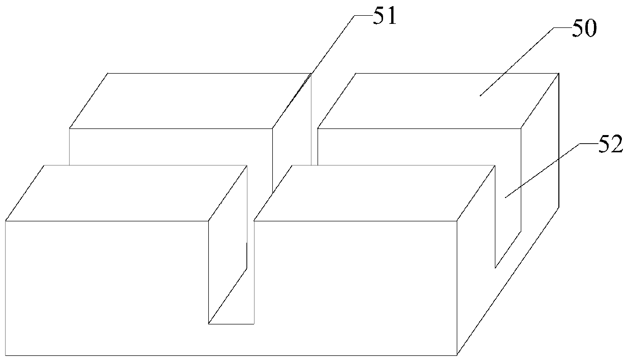
The invention relates to an infusion stopping clip device for an indwelling needle. The infusion stopping clip device comprises an infusion stopping clip which is provided with a central through hole,an anti-counterflow through hole, a flushing through hole, and two elastic grooves. The infusion stopping clip sleeves an extension tube via the central through hole, and the anti-counterflow throughhole and the flushing through hole horizontally extend along both sides of the central through hole, respectively. The two elastic grooves are respectively arranged at both sides of the anti-counterflow through hole and along a same axial direction as the anti-counterflow through hole. The elastic grooves are deformed when being squeezed. The anti-counterflow through hole and the flushing throughhole have elongated cross sections. The width of the anti-counterflow through hole and the flushing through hole is less than the outer diameter of the extension tube. The width of the anti-counterflow through hole is greater than the width of the flushing through hole. According to the invention, when the infusion stops, the extension tube is squeezed by restoring deformation of the elastic grooves, so that trace amount of fluid is discharged out of a cannula, thereby achieving the purposes of preventing blood from flowing back. The extension tube moves into the flushing through hole, and due to moving of the extension tube, the extension tube is squeezed by the flushing through hole, thereby achieving automatic flushing with pressure.

Description

technical field [0001] The invention relates to the technical field of medical instruments, in particular to an indwelling needle liquid stop clip device. Background technique [0002] Venous indwelling needle is a common medical device in nursing work. It is easy to use and reduces the number of punctures for patients, thereby reducing repeated punctures during clinical infusion, reducing the pain of puncture for patients and the workload of clinical nurses. It has been widely used in clinical practice today. [0003] During the indwelling needle, the liquid flow channel must be blocked with a liquid stop clip. After closing the liquid stop clip, it is easy to cause negative pressure in the catheter during the non-infusion process. Even a slight negative pressure will cause blood to flow into the indwelling catheter. In the cannula of the needle, thrombus will soon form and block the cannula, causing harm to the human body. For this reason, in recent years, there have bee...

Claims


Application Information

Patent Timeline
IPC IPC(8): A61M39/28A61M5/158
CPCA61M5/158A61M39/28
Inventor 谢世庚汪洋徐会斌
Owner JIANGXI FENGLIN MEDICAL APPLIANCE
Learn More