
Bar feeding machine

A bar and material machine technology, applied in the field of bending machine feeding and unloading devices, can solve the problems of reducing the efficiency of construction, uneven placement, accuracy impact, etc., to reduce cumbersomeness, accurate and efficient material moving and sorting Effect

Pending Publication Date: 2020-05-08
CHANGGE JUBA MACHINERY
View PDF0 Cites 1 Cited by
  • Summary
  • Abstract
  • Description
  • Claims
  • Application Information

AI Technical Summary

Problems solved by technology

[0002] Now, in the process of bending the steel bar, the steel bar bending machine is used for bending. In the process of using the bending machine, in order to make the feeding more accurate and stable, it is used to feed the material from the top of the bending machine. At present, In the process of feeding, most of them are fed by manual lifting, which greatly reduces the efficiency of construction. However, when using conventional machinery for feeding, the rod materials are randomly dropped and placed unevenly in the storage. In this way, after feeding, it will affect the accuracy of the bending operation of the bar; and, in the process of bending the steel bar, most of the steel bar bending processing plants use manual manual bending. After the steel bar is placed in the bending part of the bending machine, the bending machine is turned on, and after the bending is completed, the steel bar after bending at both ends is manually taken out
After a long time of operation, workers often have the problem of heavy labor load, which affects the stability and efficiency of steel bars during bending

Method used


Image

  • Bar feeding machine
  • Bar feeding machine
  • Bar feeding machine

Examples


Embodiment Construction

[0032] In order to make the object, technical solution and advantages of the present invention clearer, the present invention will be further described in detail below in conjunction with the embodiments and accompanying drawings. It should be understood that the specific embodiments described here are only used to explain the present invention, not to limit the present invention.

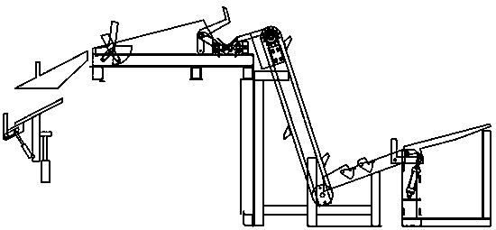
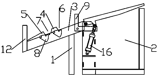
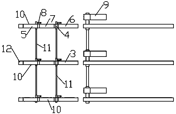
[0033] Please refer to figure 1 , figure 2 , image 3 as well as Figure 4 As shown, a bar material loading machine is provided with end-to-end sorting and loading devices, alignment buffer devices, and feeding and unloading devices in sequence along the direction of material transportation;

[0034]The sorting and feeding device includes a sorting part 1 and a material receiving part 2 for displaying materials. The picking unit 1 is arranged on the downstream side of the receiving unit 2;

[0035] The alignment and buffering device includes an end-to-end connection feeding part 14, a buffer ...


PUM


Abstract

The invention discloses a bar feeding machine, and relates to the field of bending machine supplying-unloading devices. The bar feeding machine comprises a sorting feeding device, an alignment buffering device and a discharging unloading device which are sequentially arranged in the material conveying direction and are connected end to end; the sorting feeding device comprises a sorting part and acarrying part for placing materials, the sorting part and the placing end of the carrying part are of inclined structures connected end to end, and the sorting part is arranged on the downstream sideof the carrying part; the alignment buffering device comprises a feeding part, a buffering alignment part and a discharge storage part which are sequentially arranged in the material conveying direction and connected end to end, and the feed end of the feeding part is connected with the unloading end of the sorting part; and the discharging unloading device comprises a storage frame arranged on the upper portion of a bar bending machine, a discharging unloading part is arranged on the lower portion of the storage frame, and the feed end of the storage frame communicates with the discharge storage part. Thus, the purpose that bars are precisely conveyed from the lower portion in an automatic assembly line mode to be aligned, then fed from the upper portion of the bending machine, and subjected to bending operation through the bending machine can be achieved.

Description

technical field [0001] The invention relates to the field of feeding and unloading devices for bending machines, in particular to a bar feeding machine. Background technique [0002] Now, in the process of bending the steel bar, the steel bar bending machine is used for bending. In the process of using the bending machine, in order to make the feeding more accurate and stable, it is used to feed the material from the top of the bending machine. At present, In the process of feeding, most of them are fed by manual lifting, which greatly reduces the efficiency of construction. However, when using conventional machinery for feeding, the rod materials are randomly dropped, and the left and right are placed unevenly in the storage. In this way, after feeding, it will affect the accuracy of the bending operation of the bar; and, in the process of bending the steel bar, most of the steel bar bending processing plants use manual manual bending. After the steel bars are placed in th...

Claims


Application Information

Patent Timeline
IPC IPC(8): B21F23/00B21F1/00
CPCB21F1/00B21F23/007
Inventor 王华民
Owner CHANGGE JUBA MACHINERY
Learn More