Three-dimensional optical rotating platform

A rotating platform, three-dimensional optical technology, applied in the field of machinery, can solve the problems of jitter, affect the test effect, prolong the test time, etc., and achieve the effect of preventing collision

Pending Publication Date: 2020-05-08
福建水利电力职业技术学院
View PDF6 Cites 0 Cited by
  • Summary
  • Abstract
  • Description
  • Claims
  • Application Information

AI Technical Summary

Problems solved by technology

[0002] In this era of advanced technology, various industries will do many related experiments, such as the field of optics. Optical experiments need to use related equipment to study and analyze light. During the analysis process, the equipment may need to be rotated in three dimensions, but many existing It is assumed that the three-dimensional rotating platform will vibrate during the rotation process, which may greatly improve the experimental efficiency for some detections that have been focused or need to maintain high-precision angles.
[0003] In the prior art, the two relatively rotating platforms are directly connected by a rotating shaft, which is completely suitable for equipment with low precision, but for some similar optical equipment inspection processes, the test effect may be affected by the jitter or Extend the experiment time

Method used


Image

  • Three-dimensional optical rotating platform
  • Three-dimensional optical rotating platform
  • Three-dimensional optical rotating platform

Examples


Embodiment Construction

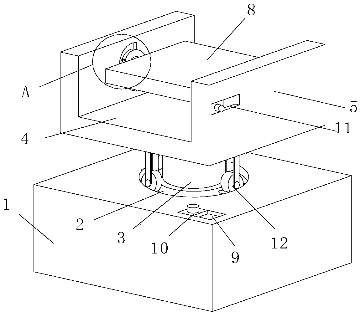
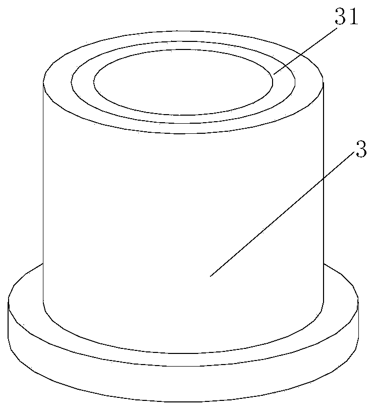
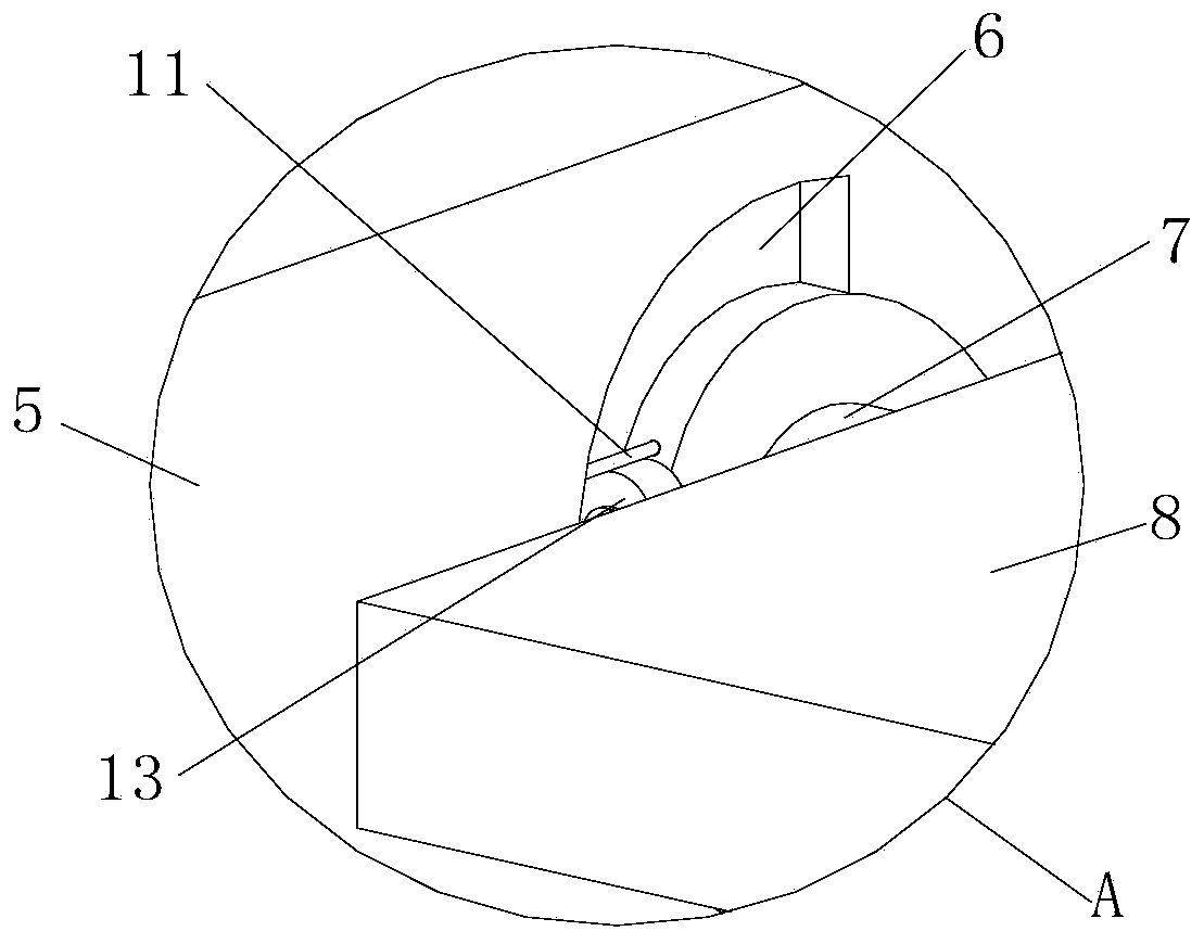
[0035] Such as Figure 1-3 As shown, a three-dimensional optical rotating platform includes a base 1, a support base 4 with side baffles 5 at both ends, a mounting plate 8, a first drive and a second drive, and the support base 4 is set through a first rotating shaft 3 On the base 1 , both ends of the mounting plate 8 are rotationally connected to the opposite side baffles 5 through the second rotating shaft 7 . The first drive is arranged in the base 1, and the first drive is connected to the first rotating shaft 3, the second drive is fixed on the side baffle 5, and the driving end of the second drive is fixedly connected to the second rotating shaft 7 . The first drive drives the support seat 4 on the first rotating shaft 3 to rotate horizontally relative to the base 1 , and the second drive drives the second rotating shaft 7 to rotate relative to the side baffles 5 on both sides.

[0036] The base 1 and the side baffle 5 are provided with a groove with a set arc at a set...


PUM


Abstract

The invention discloses a three-dimensional optical rotating platform. The three-dimensional optical rotating platform includes a base, a supporting seat provided with side baffles at both ends and amounting plate. The supporting seat is arranged on the base through a first rotating shaft. The side surfaces at two ends of the mounting plate are rotatably connected with the opposite side baffles through second rotating shafts respectively, supporting frames are arranged on the side surface on which the rotating shaft is arranged of the supporting seat and the side surface on which the rotatingshafts are arranged of the mounting plate, and rollers which roll in corresponding grooves are arranged at the bottom ends of the supporting frames. According to the three-dimensional optical rotating platform, the supporting frames are arranged on two sides of the rotating shafts, the rollers are arranged at the bottoms of the supporting frames, the rollers move in the corresponding grooves, therollers carry the weight of all components on the supporting seat and the mounting plate during the rotation of the rotating shafts, in this way, the rotating shafts cannot be shaken due to the needof rotation while receiving the carrying force in the rotation process, and the device realizes the horizontal rotation and pitching motion of a detection component on the mounting plate.

Description

technical field [0001] The invention relates to the mechanical field, in particular to a three-dimensional optical rotating platform. Background technique [0002] In this era of advanced technology, various industries will do many related experiments, such as the field of optics. Optical experiments need to use related equipment to study and analyze light. During the analysis process, the equipment may need to be rotated in three dimensions, but many existing Assuming that the three-dimensional rotating platform will shake during the rotation process, it may be possible for some detections that have been focused or need to maintain high-precision angles, and the smooth rotation greatly improves the experimental efficiency. [0003] In the prior art, the two relatively rotating platforms are directly connected by a rotating shaft, which is completely suitable for equipment with low precision, but for some similar optical equipment inspection processes, the test effect may be...

Claims


Application Information

Patent Timeline
Patent Type & Authority Applications(China)
IPC IPC(8): B25H1/14G01M11/00B01L9/02
CPCB25H1/14G01M11/00B01L9/02
Inventor 周甫孙威朱庆喜王振东张瑞芬肖祥
Owner 福建水利电力职业技术学院
Why Eureka
Try Eureka