
A fan blade structure for an oven

A technology of fan blades and ovens, applied in the field of ovens, can solve the problems of spatial streamline disorder, temperature uniformity not as good as forward rotation temperature uniformity, fan blades not suitable for forward and reverse rotation needs, etc., to achieve consistent flow field streamlines , the effect of keeping the air volume consistent

Active Publication Date: 2021-05-18
NINGBO FOTILE KITCHEN WARE CO LTD
View PDF7 Cites 0 Cited by
  • Summary
  • Abstract
  • Description
  • Claims
  • Application Information

AI Technical Summary

Problems solved by technology

[0003] In the operation of the existing oven, the fan blades generally rotate in one direction, that is, clockwise (forward rotation), which will lead to poor color uniformity of the baked food, that is, half of the food has been colored, while the other half has not. Case
In order to solve the above problems, it is necessary to enable the fan blade to achieve forward and reverse rotation. Therefore, the performance of the existing fan blade in forward rotation and reverse rotation (counterclockwise rotation) is tested respectively. It can be seen from the test results that when the existing fan blade reverses When rotating, the overall uniformity of the oven is worse than when rotating forward, the space flow line is disordered, the temperature on the left and right sides of the oven is high, and the temperature in the return air area is low, the overall temperature uniformity is not as good as that of forward rotation
It can be seen that the existing fan blades used for oven heaters are not suitable for the needs of forward and reverse rotation, and need to be modified

Method used


Image

  • A fan blade structure for an oven
  • A fan blade structure for an oven
  • A fan blade structure for an oven

Examples


Embodiment 1

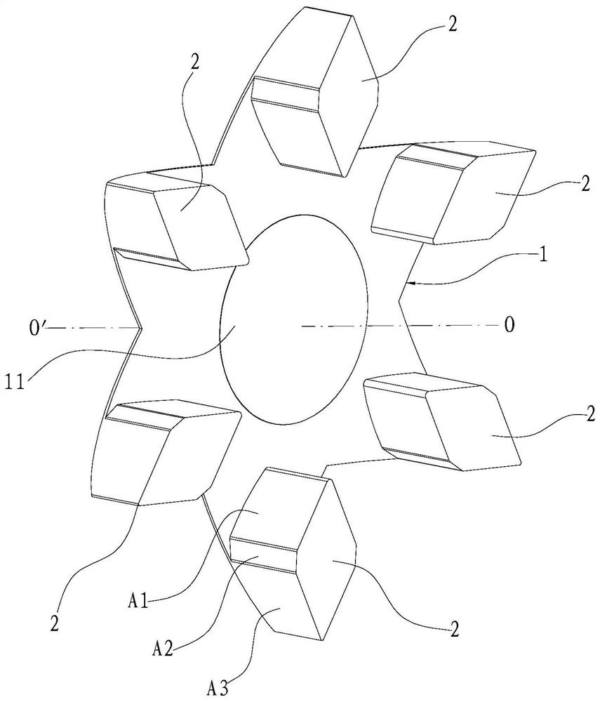
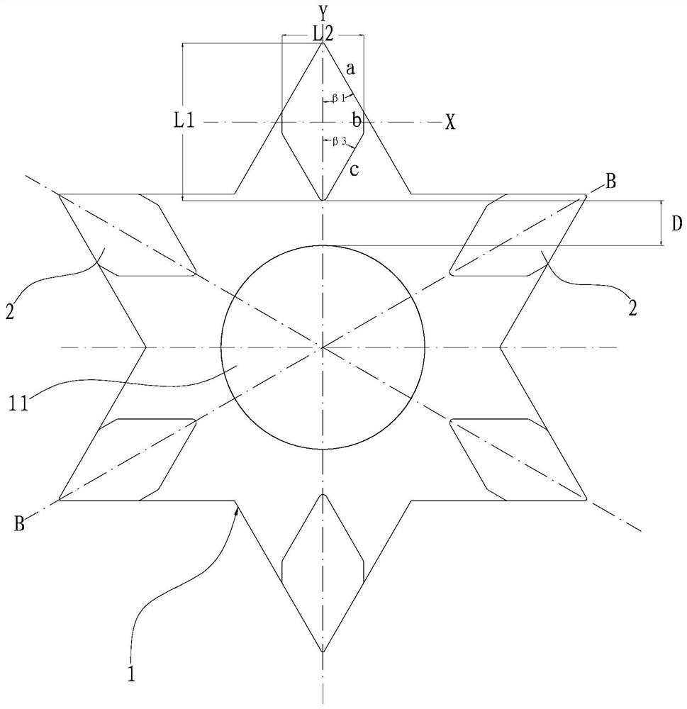
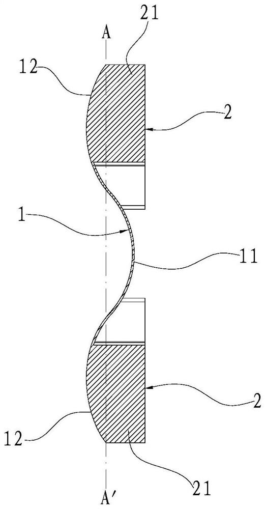
[0032] Such as Figure 1~4 As shown, a fan blade structure for an oven includes a support plate 1 and guide vanes 2 arranged on the support plate 1 . In this embodiment, the shape of any transverse section of the above-mentioned support plate 1 is centrally symmetrical, and the above-mentioned guide vanes 2 are evenly distributed on the surface of the support plate 1 at intervals in the circumferential direction around the central axis OO' of the support plate 1, The outermost end of each guide vane 2 all overlaps with the outermost end of the support plate 1 plate surface where it is located, and each guide vane 2 is arranged along the radial direction of the support plate 1 plate surface where it is located, and each guide vane 2 Any transverse section has a first axis of symmetry Y extending radially along the surface of the support plate 1 where it is located.

[0033] In this embodiment, when the fan blade structure is placed horizontally, the horizontal projection of th...

Embodiment 2

[0041] Such as Figure 5 As shown, the difference from the embodiment is that in this embodiment, the size of each sharp angle of the horizontal projection of the support plate 2 is 90°, and each guide vane 2 is located at the outermost surface of the support plate 1 where it is located. The part 21 above the transverse section AA' of the support plate 1 where the end is located, any transverse section of this part 21 is square as a whole, and β 1 and beta 3 are 45 degrees, and β 2 is 0 degrees.

Embodiment 3

[0043] Such as Figure 6 and 7 As shown, the difference from Embodiment 1 is that the shape of each guide vane 2 in this embodiment is plate-shaped. At this time, from the above formula, the entire outer surface of the guide vane 2 is the effective windward area, and the positive and negative Maximum air flow.


PUM


Abstract

The invention relates to a fan blade structure for an oven, which comprises a support plate and a guide vane arranged on the support plate. The central axis is centered and evenly distributed on the surface of the support plate along the circumferential interval, the outermost ends of each guide vane overlap with the outermost end of the support plate surface where it is located, and each guide vane is along The radial arrangement of the support plate surface, any transverse section of each guide vane has a first symmetry axis extending radially along the support plate surface where it is located. In the present invention, through the design of the shape of the support plate and the guide vane in the fan blade structure, and the design of the setting position of the guide vane on the support plate, the flow field streamlines of the fan blade structure when it is reversing inside the oven are maintained. Consistent, so that the same air volume can be generated during forward and reverse rotation, and then the fan blade structure in the present invention is suitable for forward and reverse rotation of the oven hot air blower.

Description

technical field [0001] The invention relates to the field of ovens, in particular to a fan blade structure for an oven. Background technique [0002] Generally, the back of the oven liner is equipped with a hot air fan, which can enhance the convective heat transfer inside the oven, thereby improving the baking effect of the oven to a certain extent. The hot air blower in the prior art generally adopts fan blades with six uniformly distributed blades, and the installation angle of the blades is 20°. For example, the Chinese utility model patent "An Embedded Oven Hot Air Fan" whose patent number is ZL200820097538.9 (authorized announcement number is CN201166005Y) discloses an embedded oven hot air fan, including a wheel hub and more than one fan connected to the wheel hub. leaf. [0003] In the operation of the existing oven, the fan blades generally rotate in one direction, that is, clockwise (forward rotation), which will lead to poor color uniformity of the baked food, t...

Claims


Application Information

Patent Timeline
Patent Type & Authority Patents(China)
IPC IPC(8): F04D29/26A47J37/06
CPCA47J37/0664F04D29/26
Inventor 陈祖向杨均曹骥
Owner NINGBO FOTILE KITCHEN WARE CO LTD
Learn More