Fan and using method thereof

A fan and fan blade technology, applied in the field of operation and maintenance equipment, can solve the problems of no heat dissipation in the power distribution room, reduced operation and maintenance efficiency, and inability to cool down in time.

Pending Publication Date: 2021-03-16
GUANGDONG POWER GRID CO LTD +1
View PDF6 Cites 0 Cited by
  • Summary
  • Abstract
  • Description
  • Claims
  • Application Information

AI Technical Summary

Problems solved by technology

[0002] The power distribution room is used to accommodate servers, routers, network switches, and distribution frames. However, the power distribution room used in the related art has the following problems: the internal temperature of the power distribution room cannot be too high in summer, and the existing The power distribution room has no heat dissipation function. At the same time, it is used for a long time. The electrical equipment inside the power distribution room is prone to failure and burning, which will cause danger. Operation and maintenance efficiency
[0003] In the power distribution room, in order to cool down the operation and maintenance personnel and various electrical equipment in the power distribution room, fans or air conditioners can be used, but the current fans can only shake their heads in situ, and among the objects to be cooled, the higher temperature cannot be cooled in time , making the overall cooling effect uneven

Method used


Image

  • Fan and using method thereof
  • Fan and using method thereof
  • Fan and using method thereof

Examples


Embodiment Construction

[0037] In order to make the technical problems solved by the present invention, the technical solutions adopted and the technical effects achieved clearer, the technical solutions of the embodiments of the present invention will be further described in detail below in conjunction with the accompanying drawings. Obviously, the described embodiments are only the technical solutions of the present invention. Some, but not all, embodiments. Based on the embodiments of the present invention, all other embodiments obtained by those skilled in the art without creative efforts fall within the protection scope of the present invention.

[0038] In the description of the present invention, unless otherwise clearly specified and limited, the terms "connected", "connected" and "fixed" should be understood in a broad sense, for example, it can be a fixed connection, a detachable connection, or an integrated ; It can be a mechanical connection or an electrical connection; it can be a direct...


PUM


Abstract

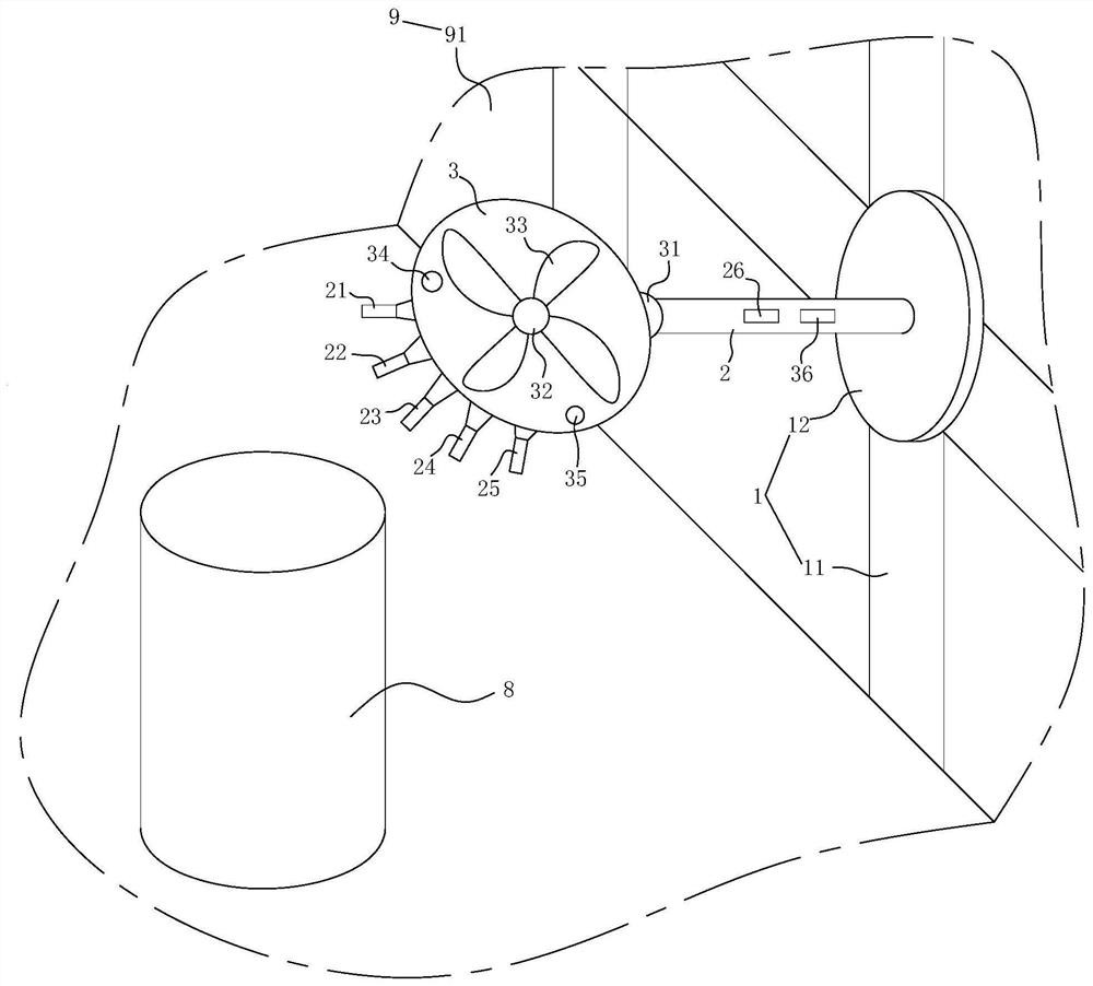
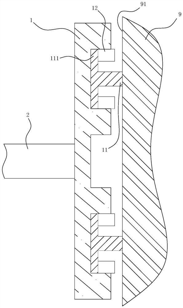
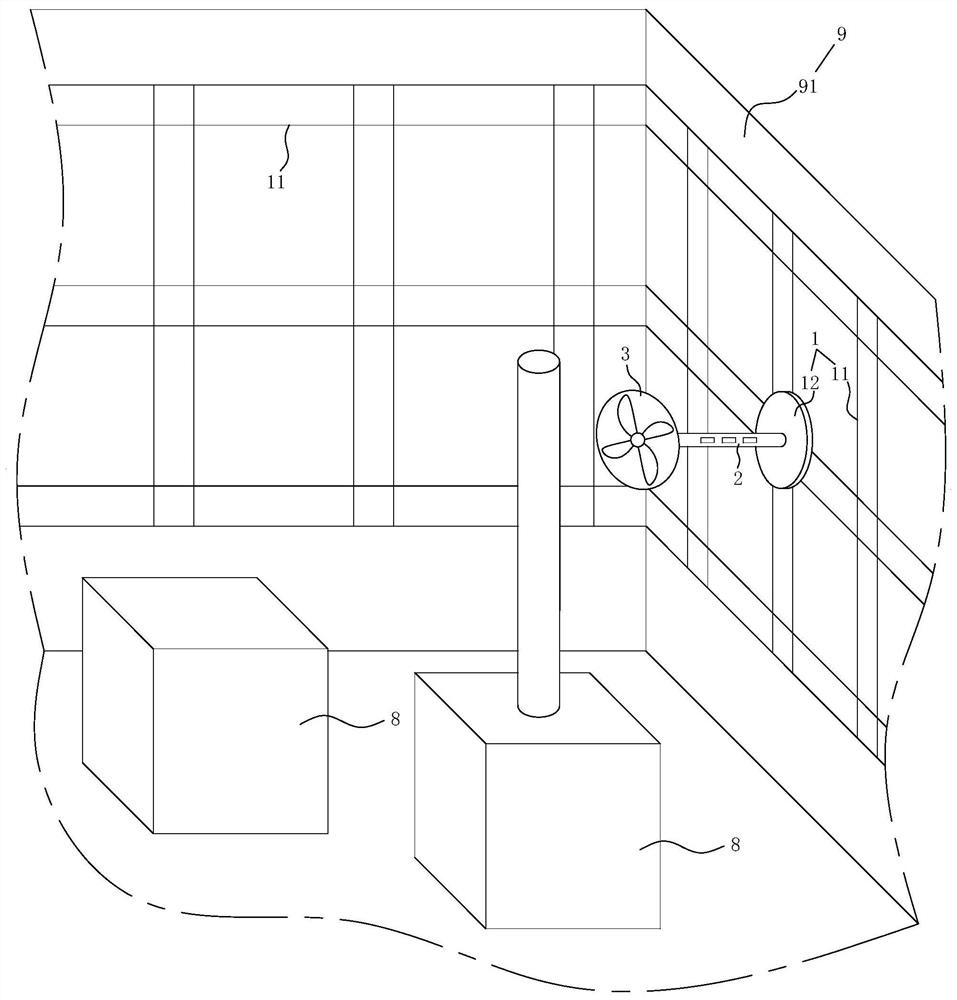
The invention relates to the technical field of operation and maintenance equipment, and particularly discloses a fan and a using method thereof. The fan comprises a moving device arranged on the inner cavity surface of a power distribution room body, a supporting rod and a fan body are arranged on the moving device, a first driving assembly and a second driving assembly are arranged on the fan body, the first driving assembly is used for driving the fan body to rotate relative to the supporting rod, and fan blades are arranged on the second driving assembly. The second driving assembly is used for driving the fan blades to rotate, a laser scanning radar, an infrared temperature measuring assembly and a controller are arranged on the fan body, and the laser scanning radar, the infrared temperature measuring assembly, the first driving assembly, the second driving assembly and the moving device are in communication connection with the controller. The controller drives the moving deviceto move on a plurality of inner cavity faces of the power distribution room body, drives the first driving assembly to drive the fan body to face an object and drives the second driving assembly to drive the fan blades to rotate. The fan can automatically adjust the cooling sequence, and the cooling effect is uniform.

Description

technical field [0001] The present invention relates to the technical field of operation and maintenance equipment, in particular to a fan and its usage method. Background technique [0002] The power distribution room is used to accommodate servers, routers, network switches, and distribution frames. However, the power distribution room used in the related art has the following problems: the internal temperature of the power distribution room cannot be too high in summer, and the existing The power distribution room has no heat dissipation function. At the same time, it is used for a long time. The electrical equipment inside the power distribution room is prone to failure and burning, which will cause danger. Operation and maintenance efficiency. [0003] In the power distribution room, in order to cool down the operation and maintenance personnel and various electrical equipment in the power distribution room, fans or air conditioners can be used, but the current fans ca...

Claims


Application Information

Patent Timeline
Patent Type & Authority Applications(China)
IPC IPC(8): F04D25/08F04D27/00F24F3/14F24F5/00F24F11/89
CPCF04D25/08F04D27/00F04D27/004F24F5/0042F24F3/14F24F11/89
Inventor 邱灿树
Owner GUANGDONG POWER GRID CO LTD
Why Eureka
Try Eureka