
An underwater flow-induced cavity noise control device

A cavity noise and control device technology, applied in the direction of fluid flow, mechanical equipment, etc., can solve the problems of low self-noise, high applicability, etc., achieve flexible installation, reduce velocity gradient, and suppress cavity shear layer oscillation Effect

Active Publication Date: 2021-09-28
NAVAL UNIV OF ENG PLA
View PDF5 Cites 0 Cited by
  • Summary
  • Abstract
  • Description
  • Claims
  • Application Information

AI Technical Summary

Problems solved by technology

[0005] The above two types of cavity noise control devices applied in the air can be used as a reference for the control of cavity noise in water, but there are still areas to be improved in terms of low self-noise, high applicability, and ease of installation and use.

Method used


Image

  • An underwater flow-induced cavity noise control device
  • An underwater flow-induced cavity noise control device
  • An underwater flow-induced cavity noise control device

Examples


Embodiment Construction

[0028] In order to make the object, technical solution and advantages of the present invention clearer, the present invention will be further described in detail below in conjunction with the accompanying drawings and embodiments. It should be understood that the specific embodiments described here are only used to explain the present invention, not to limit the present invention. In addition, the technical features involved in the various embodiments of the present invention described below can be combined with each other as long as they do not constitute a conflict with each other.

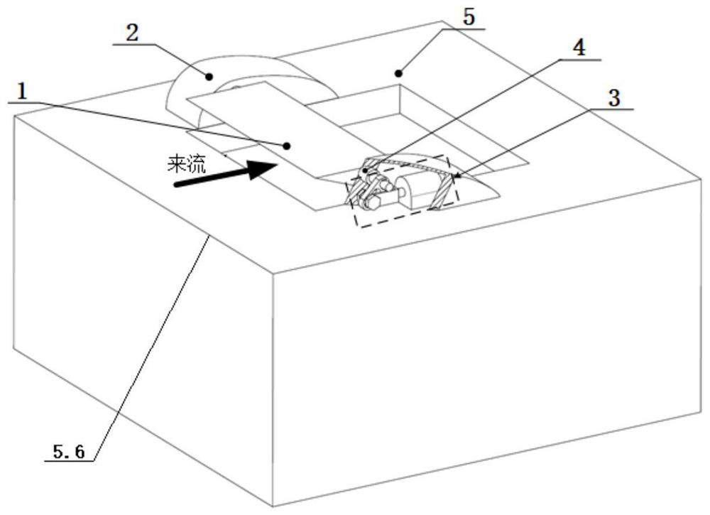
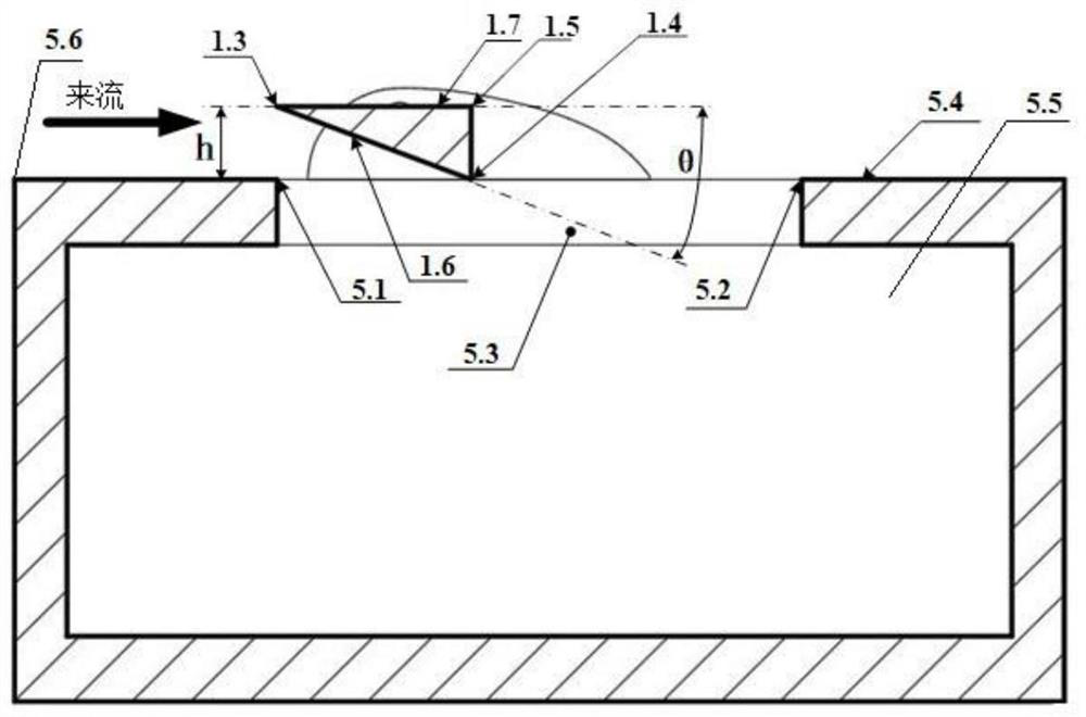
[0029] Such as Figure 1 ~ Figure 4 As shown, an underwater flow-induced cavity noise control device includes a bracket 2, a drive unit 3 and a split body 1, wherein,

[0030] The bracket 2 is installed on the upper surface 5.4 of the cavity body 5, the upper surface 5.4 of the cavity body 5 has a cavity communicating with the inner cavity 5.5 of the cavity body 5, and the inside of the bracket...


PUM


Abstract

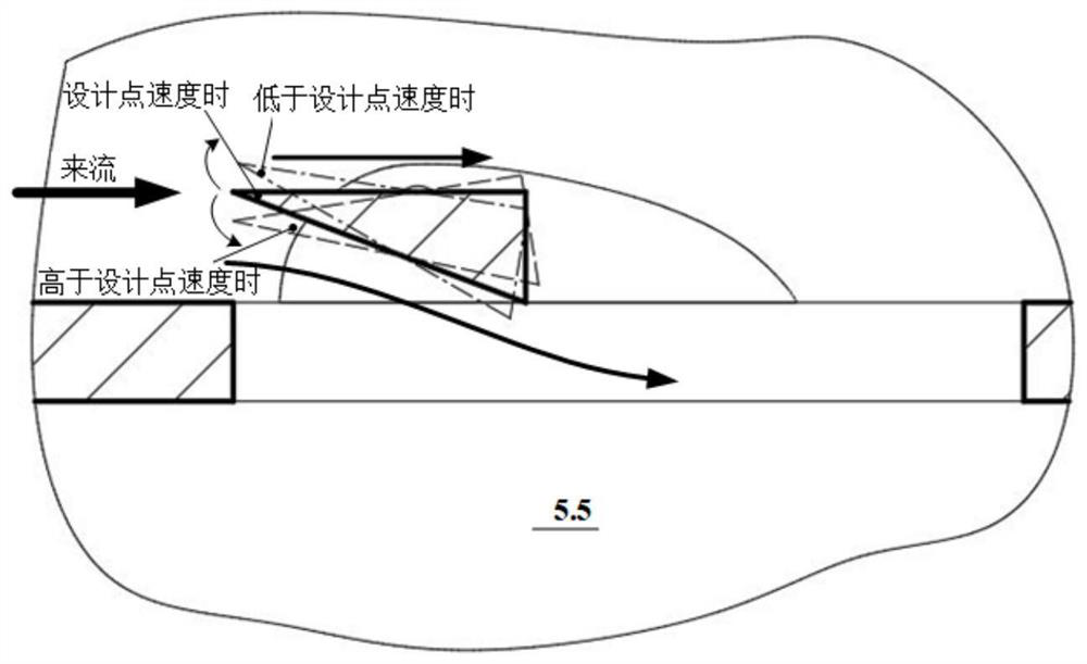
The invention discloses an underwater flow-induced cavity noise control device, which comprises a bracket, a drive unit and a split body, the bracket is installed on the upper surface of a cavity body, and the upper surface of the cavity body has a The mouth of the lumen that is connected to the cavity; the bracket installs the sub-body at a position corresponding to the cavity, and the sub-body includes a straight triangular prism and a protruding shaft arranged on the straight triangular prism, at least one of which The protruding shaft is set on a bottom surface; the three sides of the right triangular prism are respectively a split flow face facing the incoming flow and facing the cavity body, a back flow face away from the incoming flow, and a connection between the split flow surface and the back flow surface. The guide surface of the flow surface; the extension shaft is connected with the drive unit for driving the right triangular prism to rotate around the axis of the extension shaft. On the one hand, the separating fluid of the present invention suppresses the separation of the boundary layer at the mouth of the mouth; on the other hand, it reduces the velocity gradient of the shear layer at the mouth of the mouth, effectively inhibits the oscillation of the shear layer at the mouth of the mouth, and reduces the flow-induced cavity noise.

Description

technical field [0001] The invention belongs to the technical field of hydrodynamic noise control, and more specifically relates to an underwater flow-induced cavity noise control device. Background technique [0002] Cavities widely exist in the openings of underwater vehicles. When the turbulent boundary layer on the surface of the vehicle flows through these openings, a turbulent shear layer is formed at the orifice (cavity opening). The interaction between the edge and the fluid in the cavity will form a relatively severe self-sustained oscillation at the mouth of the cavity, causing large velocity and pressure fluctuations, and radiating strong line spectrum noise, that is, cavity noise, which seriously affects the underwater vehicle. concealment. [0003] The mechanism of cavity noise is very complex. Generally speaking, typical cavity noise includes the following mechanism features: the turbulent boundary layer separates at the leading edge of the cavity and forms an...

Claims


Application Information

Patent Timeline
Patent Type & Authority Patents(China)
IPC IPC(8): F15D1/00
CPCF15D1/002F15D1/0055
Inventor 徐荣武章文文程果余文晶
Owner NAVAL UNIV OF ENG PLA
Learn More