Heat exchanger for air conditioning system

A technology for heat exchangers and air-conditioning systems, applied in the field of operating the heat exchangers and motor vehicles, can solve problems such as uneven heating of air, and achieve the effects of small installation space, simple technical methods, and easy production

Inactive Publication Date: 2020-05-08
MAHLE INT GMBH
View PDF9 Cites 0 Cited by
  • Summary
  • Abstract
  • Description
  • Claims
  • Application Information

AI Technical Summary

Problems solved by technology

[0004] A disadvantage in the case of such conventional heat exchangers is that they produce a relatively uneven heating of the air

Method used


Image

  • Heat exchanger for air conditioning system
  • Heat exchanger for air conditioning system

Examples


Embodiment Construction

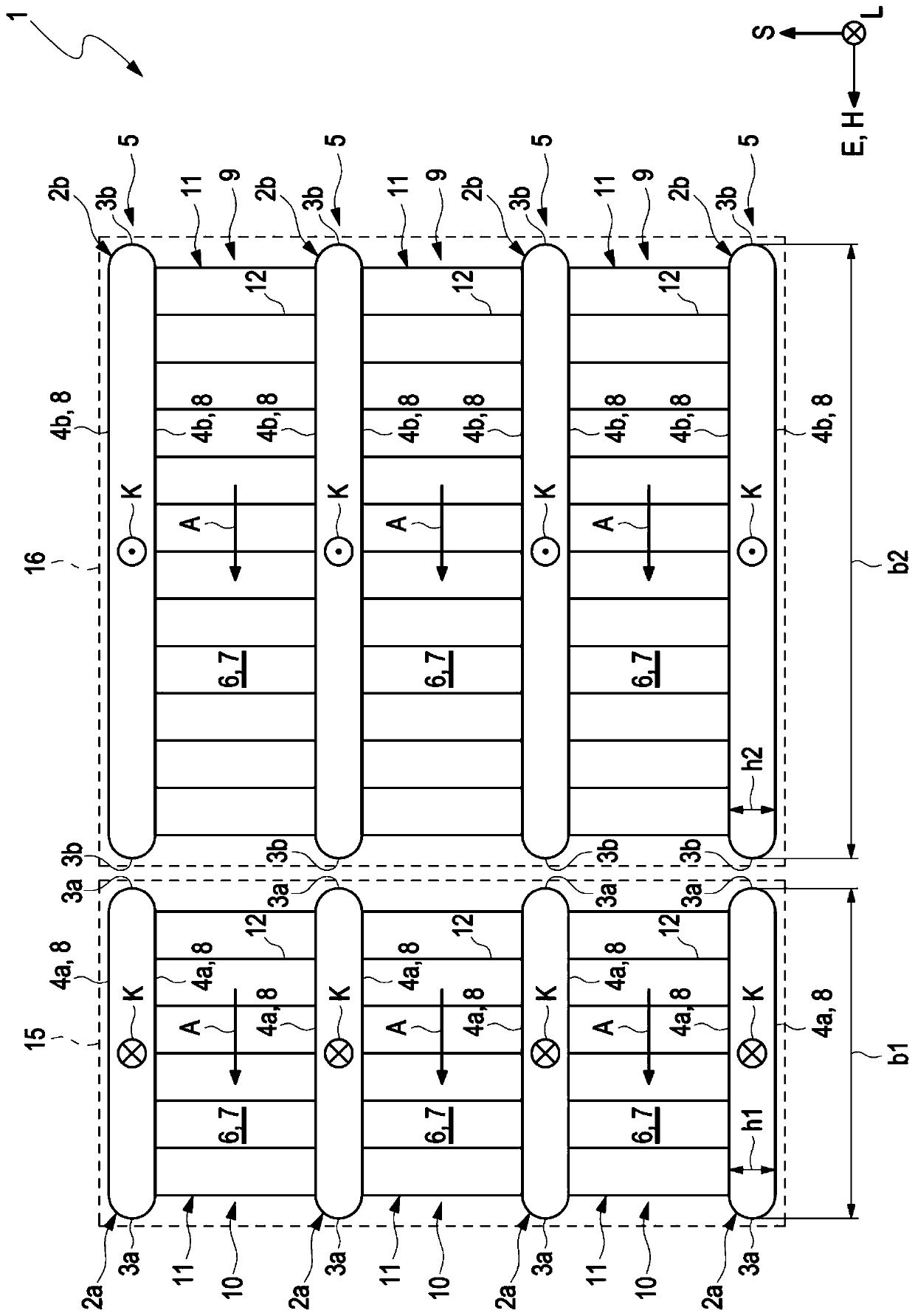
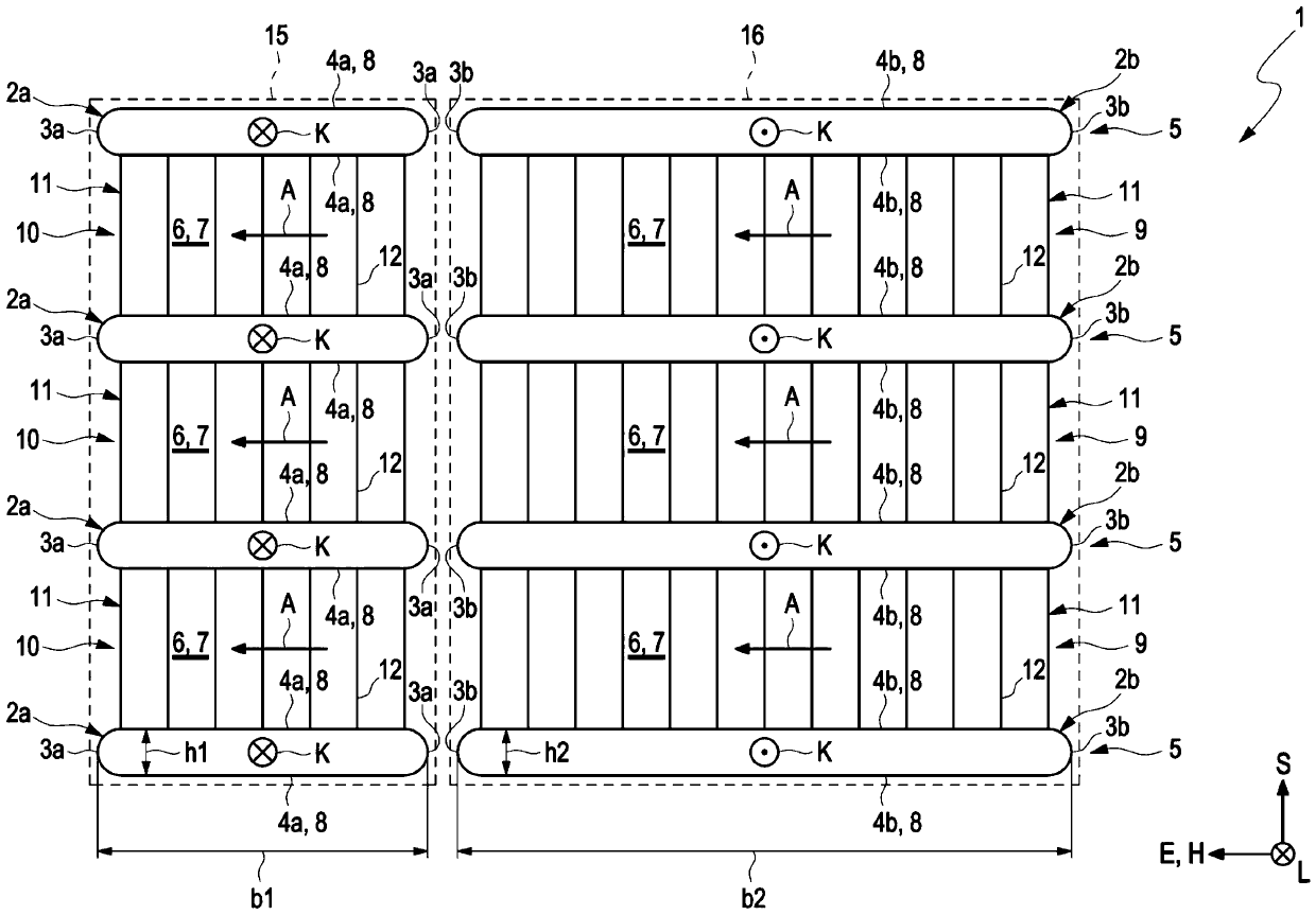
[0028] according to figure 1 , the heat exchanger 1 comprises a plurality of first flat tubes 2a, which are stacked on top of each other along the stacking direction S and thus arranged at a distance from each other and which each extend along a longitudinal direction L, the longitudinal direction L The direction L extends perpendicularly to the stacking direction S. The first flat tube 2 a is configured for the refrigerant K to flow therethrough.

[0029] In a cross-section perpendicular to the longitudinal direction L—this cross-section is in figure 1 As explained in , the first flat tubes each have two narrow sides 3a and two broad sides 4a. The heat exchanger 1 further comprises a plurality of second flat tubes 2b which are stacked on top of each other in the same manner as the first flat tubes 2a along the stacking direction S and are arranged at a distance from one another and also along The longitudinal direction L extends and is configured for refrigerant K to flow ...


PUM


Abstract

The present invention relates to a heat exchanger for an air conditioning system, comprising: at least two first flat tubes arranged at a distance from each other in a stacking direction and extendingin a longitudinal direction for a refrigerant to flow therethrough; at least two second flat tubes which are arranged at intervals along the stacking direction, extend along the longitudinal direction and are used for allowing refrigerants to flow through, wherein in the cross section perpendicular to the longitudinal direction, the first flat pipes and the second flat pipes are each provided with two narrow edges and two wide edges; a refrigerant distributor which is communicated with the first flat pipe and distributes the refrigerant to the first flat pipe and the second flat pipe; and a refrigerant collector which is communicated with the second flat pipe and collects the refrigerant flowing through the second flat pipe. The first flat tubes and the second flat tubes are each arrangednext to each other transversely to the stacking direction and form a pair of flat tubes. The width of the two wide edges of the first flat pipe in at least one flat pipe pair is smaller than that ofthe two wide edges of the second flat pipe in the same flat pipe pair.

Description

technical field [0001] The invention relates to a heat exchanger for an air conditioning system and a method for operating the heat exchanger. The invention further relates to an air conditioning system comprising such a heat exchanger and a motor vehicle comprising such an air conditioning system. Background technique [0002] Heat exchangers are used in air conditioning systems for motor vehicles in order to heat the air to be introduced into the interior of the motor vehicle. The air and the refrigerant fluidly separated and thermally connected thereto are for this purpose led through the heat exchanger so that the air can absorb heat from the refrigerant by means of thermal interaction. [0003] A heat exchanger configured as an evaporator is known, for example, from US 2013 / 0240186 A1 and from EP 1 996 890 B1. [0004] A disadvantage in the case of such conventional heat exchangers is that they produce a relatively uneven heating of the air. In other words, the air f...

Claims


Application Information

Patent Timeline
Patent Type & Authority Applications(China)
IPC IPC(8): F28D21/00
CPCF28D21/00F28D2021/008F28D1/05391F28D1/0435F28D2021/0085B60H1/00335
Inventor U·福斯特M·西弗斯
Owner MAHLE INT GMBH
Why Eureka
Try Eureka