Bonding objects together

a technology of objects and bonding, applied in the field of mechanical engineering and construction, can solve problems such as substantial forces/deformation, and achieve the effects of strong heating, high energy absorption, and potentially very fast processing

Active Publication Date: 2018-04-05
WOODWELDING
View PDF9 Cites 1 Cited by
  • Summary
  • Abstract
  • Description
  • Claims
  • Application Information

AI Technical Summary

Benefits of technology

[0021]add further functionality, such as damping or isolating, or stabilizing against torques;
[0090]The onset of liquefaction may further be controlled by geometrical structures in the form of energy directors as known from ultrasonic welding. Energy directors (or energy concentrating structures) may have the shape of ribs or humps or similar, either of the thermoplastic material or of the surface that comes into contact with the thermoplastic material. Generally, energy directors will be shaped to yield a comparably small interface area at the interface at which liquefaction is to set in to concentrate the vibration energy to this small area so that there will be a higher energy absorption per unit area that will cause a stronger heating. As soon as the temperature at these places is above the glass transition temperature, there will be enhanced internal friction, and this will further promote the energy absorption and liquefaction.

Problems solved by technology

In such situations, due to different coefficients of thermal expansion substantial forces / deformation may arise.

Method used


Image

  • Bonding objects together
  • Bonding objects together
  • Bonding objects together

Examples


Embodiment Construction

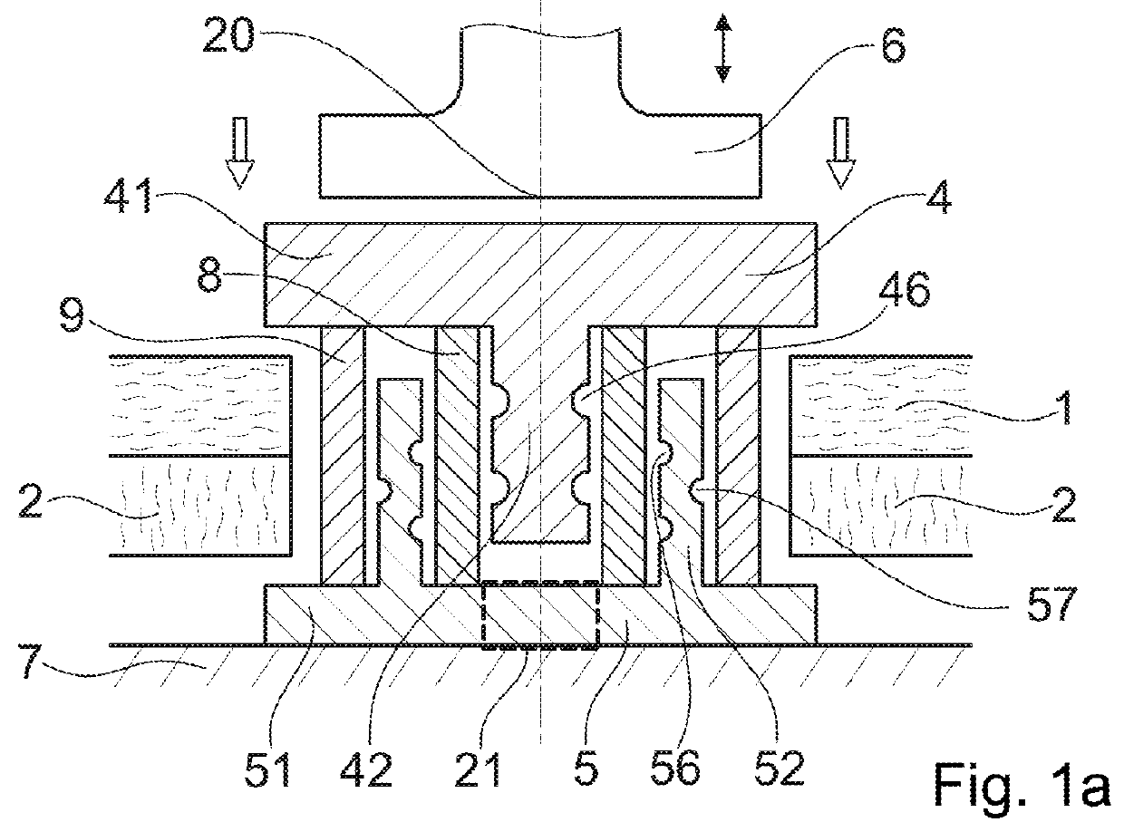
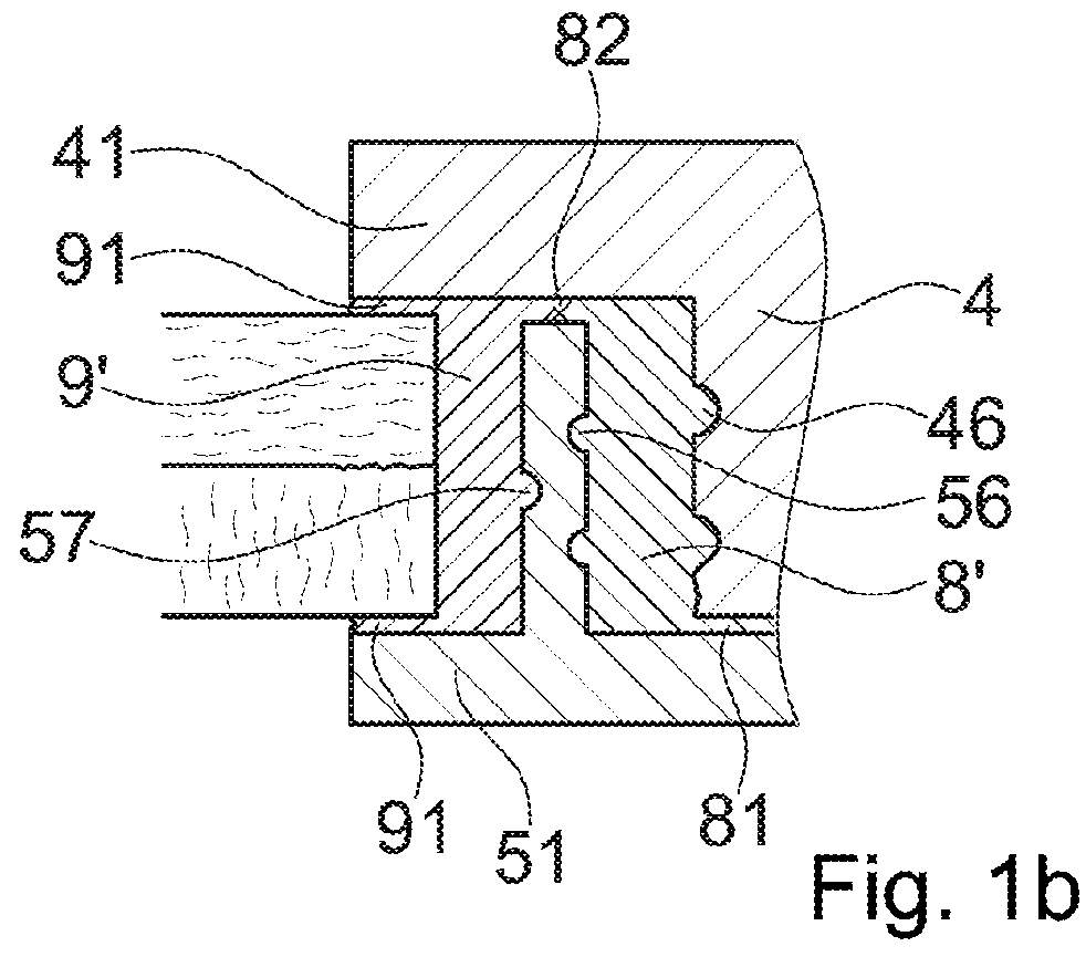
[0121]FIG. 1a depicts a basic set-up of embodiments of the invention. In the depicted embodiment, in addition to a first object 1, the connector is also to be connected to a second object 2 and to thereby connect the first and second objects 1, 2 to each other in a rivet-like manner.

[0122]The first and the second objects 1, 2 each have a through opening, the through openings being aligned with each other.

[0123]The first object 1 and the second object 2 may each, for example, be boards or sheets, for example of a metal or of a fiber reinforced composite or of foam filed carbon fiber reinforced sandwich element material. The second object may be of the same material composition as the first object or of a different material than the first object.

[0124]The first connector element 4 is of a metal, such as aluminum or an aluminum alloy or of steel. It is one-piece and has a proximal head portion 41 and a shaft portion 42.

[0125]The second connector element 5 is also of a metal, for exampl...


PUM

PropertyMeasurementUnit
frequencyaaaaaaaaaa
frequencyaaaaaaaaaa
frequencyaaaaaaaaaa

Abstract

A method of mechanically connecting a connector to a first object includes providing the first object having an opening, providing a first connector element, a second connector element, and thermoplastic material in a solid state, placing the first and second connector elements relative to the opening, causing energy to impinge on the thermoplastic material until at least a portion thereof becomes flowable and flows relative to the first and second connector elements until it is in direct (intimate) contact with both the first and second connector elements, and causing the thermoplastic material to re-solidify (for example by letting the thermoplastic material to cool down to room temperature). The re-solidified thermoplastic material locks the first and second connector elements relative to one another to yield a connector assembly that is anchored in the opening by the thermoplastic material and / or by the locking of the first and second connector elements.

Description

BACKGROUND OF THE INVENTIONField of the Invention[0001]The invention is in the fields of mechanical engineering and construction, especially mechanical construction, for example automotive engineering, aircraft construction, shipbuilding, machine construction, toy construction etc.Description of Related Art[0002]In the automotive, aviation and other industries, there has been a tendency to move away from steel constructions and to use lightweight material such as aluminium or magnesium metal sheets or die-cast parts, or carbon fiber reinforced polymers instead.[0003]The new materials cause new challenges in bonding elements of these materials—especially of bonding flattish objects (such as panels or boards) together or bonding a flattish object to an other object.[0004]Difficulties especially arise if objects of different materials are to be connected, such as two materials of the group including steel, aluminium magnesium alloys, or fiber reinforced polymers—together. Conventional ...

Claims


Application Information

Patent Timeline
Patent Type & Authority Applications(United States)
IPC IPC(8): F16B5/04B29C65/08B29C65/00
CPCF16B5/04B29C65/08B29C66/7392B29C65/48B29C66/1122B29C66/474B29C66/41B29C66/8322B29C65/562B29C66/721B29C66/727B29C66/742F16B11/006
Inventor MAYER, JORGPOSCHNER, PATRICIAKVIST, JOAKIMGERMANN, JONAS
Owner WOODWELDING
Why Eureka
Try Eureka