Rotary hammer

a rotary hammer and hammer technology, applied in the field of power tools, can solve the problems of damping member failure, ram may rebound, damping member heat generation, etc., and achieve the effects of improving catch and retain, increasing friction interference, and increasing energy absorption

Inactive Publication Date: 2006-04-25
MILWAUKEE ELECTRIC TOOL CORP
View PDF110 Cites 41 Cited by
  • Summary
  • Abstract
  • Description
  • Claims
  • Application Information

AI Technical Summary

Benefits of technology

[0017]One independent advantage of the present invention is that, in some aspects of the invention, the rotary hammer includes a two-piece ram catcher providing increased energy absorption, with the soft-plastic damping member, and increased frictional interference, with the hard friction member, to better catch and retain the ram in the idle position.
[0018]Another independent advantage of the present invention is that, in some aspects of the invention, the rotary hammer is configured to cool the damping member, for example, by passing air across the damping member, and to maintain the desired physical properties of the damping member.
[0019]Yet another independent advantage of the present invention is that, in some aspects of the invention, the rotary hammer is configured to trap a volume of air in front of the ram to absorb the force of the ram as the ram moves to the idle position and to release the volume of air to allow the ram to move to the idle position.
[0020]A further advantage of the present invention is that, in some aspects of the invention, the rotary hammer includes a rotating shaft, such as the crank shaft, defining a breather port to vent air and to reduce the pressure in the crankcase, the rotation of the shaft preventing grease from escaping through the port.
[0021]Another independent advantage of the present invention is that, in some aspects of the invention, the bit retention device is less complex and easier to operate.
[0022]Other independent features and independent advantages of the invention will become apparent to those skilled in the art upon review of the following detailed description and drawings.

Problems solved by technology

One independent problem with existing rotary hammers is that, when the hammer is changed from hammer mode to idle mode, the ram may rebound and / or be drawn by the reciprocating piston back into the hammer mode.
Another independent problem with existing rotary hammers is that, when the ram impacts the cushion or damping member (i.e., to absorb the force of the ram as it moves to idle mode), intense heat is generated on that damping member.
This intense heat can cause the physical properties of the damping member to be changed and, possibly, can cause the damping member to fail.
Yet another independent problem with existing rotary hammers is that, when the ram moves to the idle position, the air in front of the ram is vented and is not used to brake the velocity of the ram.
A further independent problem with existing power tools is that, as the power tool operates and heats up, a positive pressure builds up in the sealed crankcase, and this pressure forces air and grease past the crankcase seals and into the rest of the power tool.

Method used


Image

  • Rotary hammer
  • Rotary hammer
  • Rotary hammer

Examples


Embodiment Construction

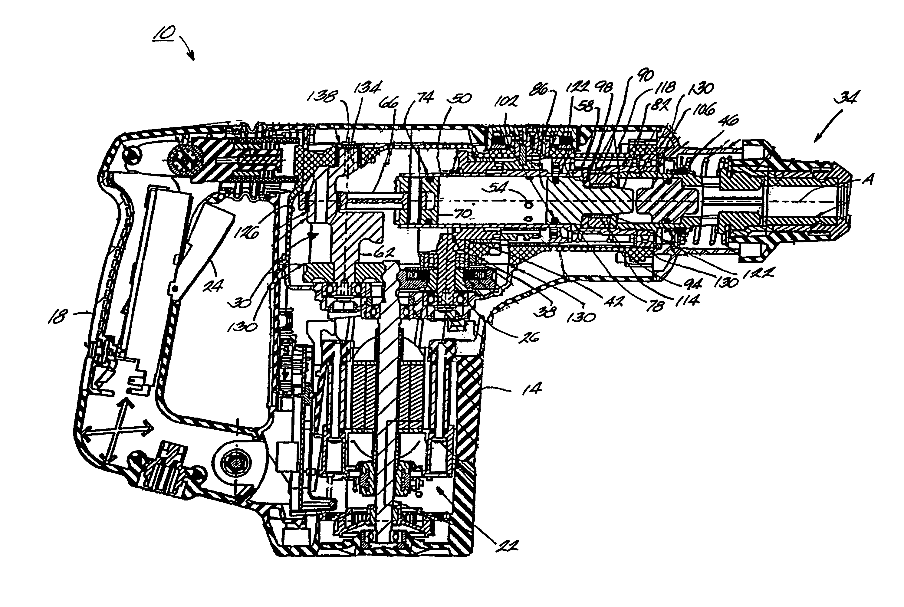
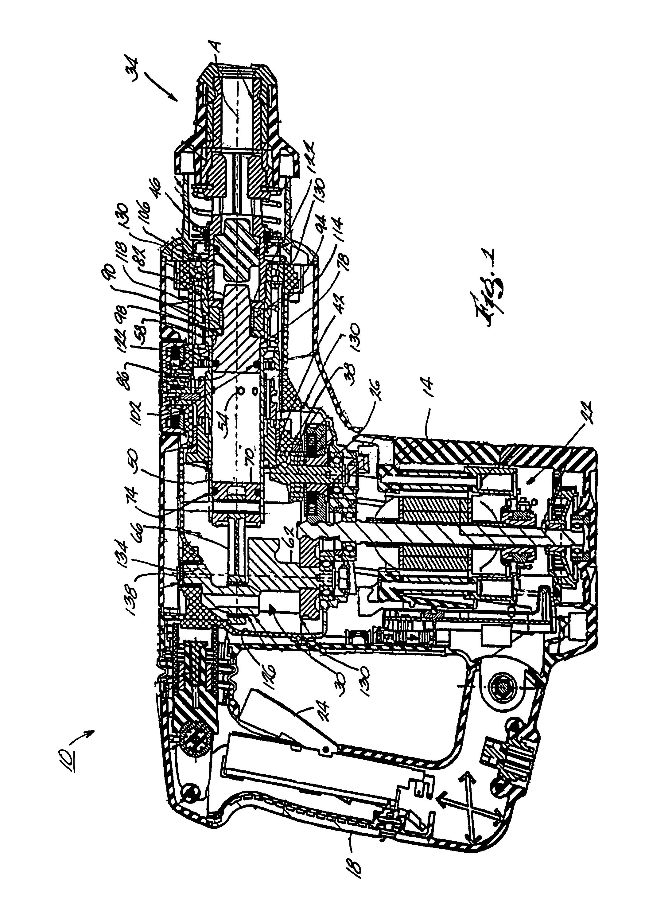
[0039]A power tool, such as, for example, a rotary hammer 10 embodying aspects of the present invention, is illustrated in FIG. 1. The hammer 10 includes a housing 14, an operator's grip or handle 18, an electric motor 22 connectable to a power source (not shown) by an on / off switch 24, a rotary drive system 26, and a reciprocating drive system 30. The hammer 10 also includes a tool holder or chuck 34 for supporting a tool element or bit B (shown in FIGS. 6A, 6B, 7 and 8). The bit B has an end for engaging a workpiece (not shown) and a rearward end. A groove G is defined adjacent the rearward end. When supported in the chuck 34, the bit B defines an axis A of the hammer 10.

[0040]As explained below, the hammer 10 selectively drives the bit B for both rotary drilling motion about the axis A and for reciprocating or hammering motion along the axis A. As also explained below, the hammer10 has a hammering mode (not shown), in which the hammer 10 provides rotary and reciprocating / hammerin...


PUM

PropertyMeasurementUnit
diameteraaaaaaaaaa
diameteraaaaaaaaaa
massaaaaaaaaaa

Abstract

A rotary hammer and a power tool. The rotary hammer is operable in an idle mode and a hammer mode and comprises a housing and a barrel positioned in the housing and having a forward portion. A ram is positioned within the barrel and is movable relative to the barrel between hammering positions and an idle position. In some aspects, a ram catcher assembly is positioned along the axis adjacent the forward portion of the barrel to releasably hold the ram in the idle position. The ram catcher assembly includes a friction member frictionally engageable with the ram and a damping member at least partially surrounding the friction member. As the ram moves to the idle position with a force, the damping member absorbs at least a portion of the force and the member applies friction to the ram.

Description

RELATED APPLICATIONS[0001]This application claims priority under 35 U.S.C. § 119 to U.S. Provisional Application Ser. No. 60 / 322,958, filed Sep. 17, 2001, now abandoned.FIELD OF THE INVENTION[0002]The present invention relates to power tools and, more particularly, to a drive system and a bit retention device for a power tool, such as a rotary hammer.BACKGROUND OF THE INVENTION[0003]In general, rotary hammers operate to impart both rotational, drilling movement and axial, hammering movement on a tool bit. In this regard, rotary hammers include both a rotary drive system and an axial drive system. One axial drive system includes a pneumatic drive system which uses an axially reciprocating piston to drive the bit.SUMMARY OF THE INVENTION[0004]One independent problem with existing rotary hammers is that, when the hammer is changed from hammer mode to idle mode, the ram may rebound and / or be drawn by the reciprocating piston back into the hammer mode.[0005]Another independent problem wi...

Claims


Application Information

Patent Timeline
Patent Type & Authority Patents(United States)
IPC IPC(8): B25D9/04B23B45/16B25D11/00B25D11/12B25D16/00B25D17/06B25D17/08B25D17/26
CPCB25D11/005B25D16/00B25D17/06B25D17/088B25D17/26B25D11/125Y10S173/03B25D2211/003B25D2211/068B25D2216/0023B25D2217/0049B25D2217/0061B25D2222/57B25D2250/035B25D2250/131B25D2250/185B25D2250/191
Inventor HETCHER, JASON D.BAUER, DAVID R.MARINKOVICH, DRAGOMIR C.WEBER, MICHAEL E.
Owner MILWAUKEE ELECTRIC TOOL CORP
Why Eureka
Try Eureka