
Formed member and manufacturing method thereof

a technology of formed members and manufacturing methods, applied in the field of formed members, can solve the problems of increasing equipment costs, increasing costs due, and reducing dimensional accuracy, and achieve the effects of improving energy absorption properties, simple structure, and increasing the ability of formed members to absorb impact energy

Active Publication Date: 2014-05-29
NIPPON STEEL CORP
View PDF1 Cites 37 Cited by
  • Summary
  • Abstract
  • Description
  • Claims
  • Application Information

AI Technical Summary

Benefits of technology

The present invention provides a formed member that can be easily manufactured and has improved energy-absorbing properties when subjected to impact loads. This is achieved by using a composite material formed by welding a reinforcing member to a ridge portion by a weld located close to the center of the ridge portion. The weld metal has higher hardness than the base metal, making it easier to form the ridge portion through hot press forming at high temperatures. The formed member is suitable for use in automobiles and the manufacturing method is simple and cost-effective.

Problems solved by technology

In the invention disclosed in Patent Document 1, a special die is necessary to form a folded portion, resulting in an increase of equipment costs.
In the inventions disclosed in Patent Documents 3-5, not only do costs increase due to forming a quench hardened portion, but there is a concern of a decrease in dimensional accuracy due to deformation of the formed member by quenching.
(a) A brazing filler metal utilizes melting of a low melting point metal. Therefore, in a hot pressing step, two steel sheets undergo press forming in a state in which a brazing filler metal in a molten state is sandwiched between them. At this time, the molten brazing filler metal penetrates into the grain boundaries of the steel, thereby causing so-called liquid metal embrittlement. In the embrittled grain boundaries, the brazing filler metal may peel off due to the strains applied by press forming, and it is very possible that a desired formed member cannot be manufactured.
(b) Even if a formed member can be manufactured, a brazing filler metal which is greatly different from steel with respect to physical properties such as strength and elongation is unavoidably present between two steel sheets. Therefore, when a formed member which is mounted on a vehicle body receives an impact load and undergoes axial crushing deformation or bending deformation, fracture easily takes place in the brazing metal itself or in the interface between the brazing metal and the steel sheets, and the fracture makes it impossible to increase the ability of the formed member to absorb impact energy.

Method used


Image

  • Formed member and manufacturing method thereof
  • Formed member and manufacturing method thereof
  • Formed member and manufacturing method thereof

Examples


example 1

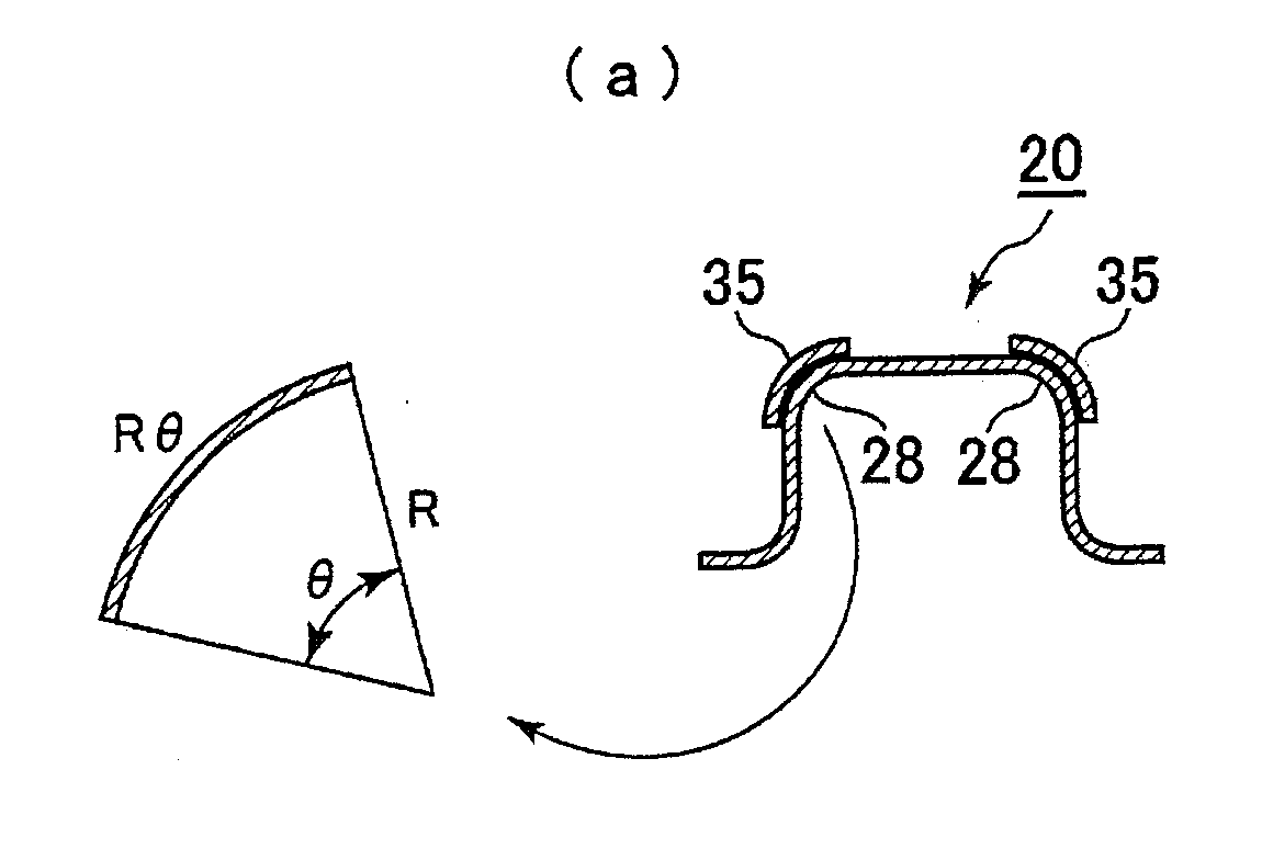
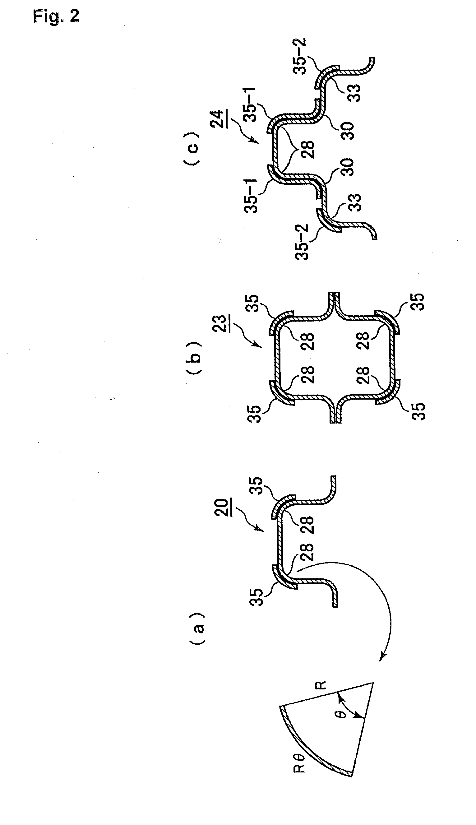
[0160]FIG. 10(a) is an explanatory view schematically showing the cross-sectional shape of a reinforcing member 35 used in this example, and FIG. 10(b) is an explanatory view showing the shape and location of reinforcing members 35 on the ridge portions 28 of a formed member 21.

[0161]FIG. 11(a) is a perspective view of a formed member 21 after spot welding of reinforcing members, and FIGS. 11(b) and 11(c) are explanatory views showing the location of spot welding of reinforcing members to a ridge portion 28 in an example of the present invention and Comparative Example 2, respectively In Comparative Example 2, no spot welds were present on the ridge portion 28.

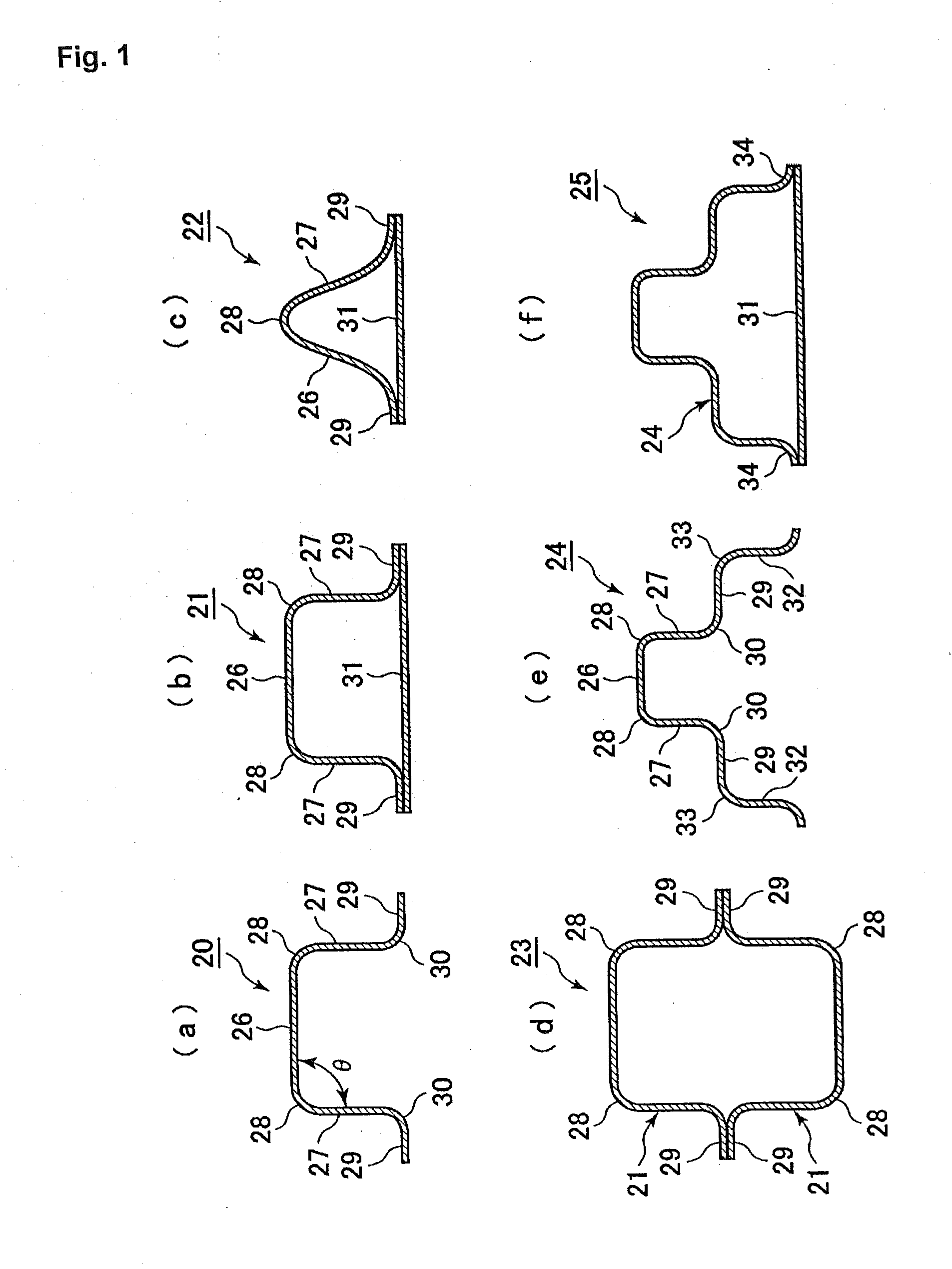
[0162]The formed members 21 used in this example had nearly the same cross-sectional shape as the formed member 21 shown in FIG. 1(a), so the same portions are indicated by the same referential numbers. In FIGS. 11(b) and 11(c), spot welds are shown by solid circles. The formed member 21 and the reinforcing members 35 both had...

example 2

[0170]A hat body portion having a hat-shaped cross section, namely, a hat-shaped to formed member was manufactured by hot press forming and was tested by a three-point bending test. This example illustrates an embodiment in which a reinforcing member 60 was provided on the inner side of ridge portions of the hat-shaped formed member.

[0171]FIG. 17(a) is an explanatory view showing the state during the three-point bending test, and FIG. 17(b) is an explanatory view showing the cross-sectional shape of the hat-shaped formed member 58.

[0172]As shown in FIG. 17(b), the hat-shaped formed member 58 comprises a hat body portion 59, a reinforcing member 60, and a hat bottom plate 61. The specifications of these components 59-61 are given below.

[0173]Hat body portion 59: a galvannealed steel sheet for hot press forming having a sheet thickness of 1.2 mm, a width of 240 mm, and a length of 600 mm

[0174]Reinforcing member 60: a galvannealed steel sheet for hot press forming having a sheet thickn...


PUM

PropertyMeasurementUnit
thicknessaaaaaaaaaa
temperatureaaaaaaaaaa
tensile strengthaaaaaaaaaa

Abstract

A formed member is provided which can be manufactured at a low cost, which has excellent dimensional accuracy, which has excellent axial crushing properties and three-point bending properties, which has excellent bending stiffness and torsional stiffness, and which is suitable for use in a component of an automobile. The formed member (20) has a reinforcing member (35) which is joined by a weld (40) provided on a ridge portion (28). It is manufactured by joining a flat sheet blank and a flat sheet reinforcing member (35) by a weld (40) and performing bending so that the weld (40) becomes a ridge portion (28).

Description

TECHNICAL FIELD[0001]This invention relates to a formed member and a method for its manufacture. Specifically, the present invention relates to a formed member which can be manufactured at a low cost and has improved dimensional accuracy, which has improved axial crushing properties and three-point bending properties or improved bending stiffness and torsional stiffness and which is therefore suitable for use in components of automobiles. It also relates to a method for its manufacture.BACKGROUND ART[0002]As is well known, almost all automobile bodies are monocoque bodies (unit construction bodies) in order to achieve both a lightweight and a high stiffness.[0003]FIG. 20 is an explanatory view schematically showing an automobile body 1.[0004]A monocoque automobile body is usually constructed by assembling a large number of components which are fabricated by press forming of a steel sheet having a thickness of at most 2.0 mm into a specified shape and connecting them by spot welding,...

Claims


Application Information

Patent Timeline
Patent Type & Authority Applications(United States)
IPC IPC(8): B32B3/28B32B15/01B21D21/00
CPCB21D5/08B21D21/00B21D22/00B21D22/208B21D35/007B21D49/00B21D53/88B23K31/022B23K2101/006B32B3/00B32B3/02B32B3/04B32B3/08B32B3/085B32B3/28B32B15/01B60R19/03B62D21/157B62D25/04Y10T29/49826Y10T428/12347Y10T428/12354Y10T428/12375Y10T428/12382Y10T428/1241Y10T428/12958B23K11/00B21D22/20B23K9/00B23K10/02
Inventor YASUYAMA, MASANORINAKAZAWA, YOSHIAKITASAKA, MASAHITOSUZUKI, TOSHIYANAKATA, MASAHIROFUJIMOTO, HIROKINISHIBATA, HITOMI
Owner NIPPON STEEL CORP
Learn More