An optical module monitoring method, monitoring device, switch and storage medium

A technology of optical modules and optical fiber modules, which is applied in the field of switches, can solve problems affecting CPU network processing capabilities, and achieve the effects of saving resources and improving network processing functions

Active Publication Date: 2022-07-08
SUZHOU METABRAIN INTELLIGENT TECH CO LTD
View PDF8 Cites 0 Cited by
  • Summary
  • Abstract
  • Description
  • Claims
  • Application Information

AI Technical Summary

Problems solved by technology

[0005] Therefore, the CPU of the switch needs to frequently schedule the I2C interface, dispersing more resources to spend on monitoring the optical module, thus affecting the network processing capability of the CPU

Method used


Image

  • An optical module monitoring method, monitoring device, switch and storage medium
  • An optical module monitoring method, monitoring device, switch and storage medium
  • An optical module monitoring method, monitoring device, switch and storage medium

Examples


Embodiment Construction

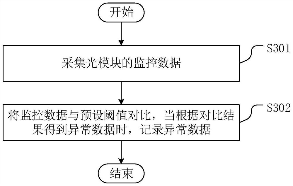
[0041] The core of the present invention is to provide a monitoring method, monitoring device, switch and storage medium for an optical module, which are used to reduce the pressure on the CPU to monitor the optical module and reduce the impact on the network processing capability of the CPU.

[0042] The technical solutions in the embodiments of the present invention will be clearly and completely described below with reference to the accompanying drawings in the embodiments of the present invention. Obviously, the described embodiments are only a part of the embodiments of the present invention, but not all of the embodiments. Based on the embodiments of the present invention, all other embodiments obtained by those of ordinary skill in the art without creative efforts shall fall within the protection scope of the present invention.

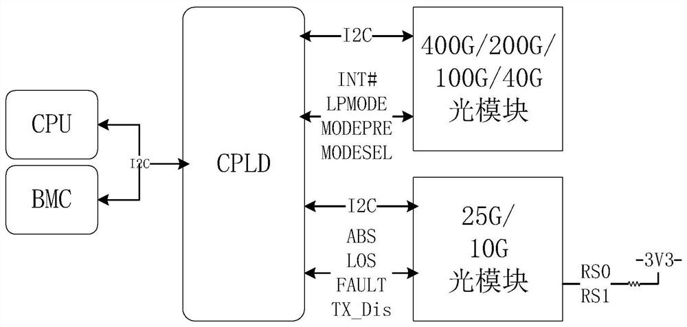
[0043] figure 2 A schematic structural diagram of a monitoring system for an optical module provided by an embodiment of the present inventio...


PUM


Abstract

The invention discloses a monitoring method for an optical module. A coprocessor arranged between a CPU and an optical module is used to collect monitoring data of the optical module, and the monitoring data is compared with a preset threshold. When abnormal data is obtained according to the comparison result , which records abnormal data for viewing by the CPU. The CPU only needs to view the abnormal data, instead of calling the I2C interface frequently to obtain the monitoring data of the optical module and do comparative analysis, which greatly saves the resources of the CPU for monitoring the optical module, so that the CPU can put more resources into the network During processing, the network processing function of the device where it is located is improved. The invention also discloses a monitoring device, a switch and a storage medium of the optical module, which have the above beneficial effects.

Description

technical field [0001] The present invention relates to the technical field of switches, and in particular, to a monitoring method for an optical module, a monitoring device, a switch and a storage medium. Background technique [0002] With the development of information technology, communication security technology is developing in a more accurate and fast direction. As the bandwidth of the switch increases, the monitoring system around the switch chip becomes more and more complex with the development of technology, which puts a huge pressure on the CPU of the switch, so that the precious processing power is allocated to the monitoring peripheral devices, and the most critical network Processing power is limited by CPU resources being occupied by peripheral devices. [0003] figure 1 It is a schematic structural diagram of a monitoring system of an optical module in the prior art. [0004] like figure 1 As shown, in the prior art, the I2C bus of the CPU is extended to ...

Claims


Application Information

Patent Timeline
Patent Type & Authority Patents(China)
IPC IPC(8): H04Q11/00H04B10/07H04B10/075
CPCH04Q11/0005H04B10/07H04B10/075H04Q2011/0037
Inventor 徐朋
Owner SUZHOU METABRAIN INTELLIGENT TECH CO LTD
Why Eureka
Try Eureka