Clamping type ear-wearing device
A clip-on, ear-worn technology, applied in on-ear/over-ear headphones, earpieces/headphone accessories, transducer shells/cabinets/stands, etc. Enhance wearing comfort and good concealment
- Summary
- Abstract
- Description
- Claims
- Application Information
AI Technical Summary
Problems solved by technology
Method used
Image
Examples
Embodiment 1
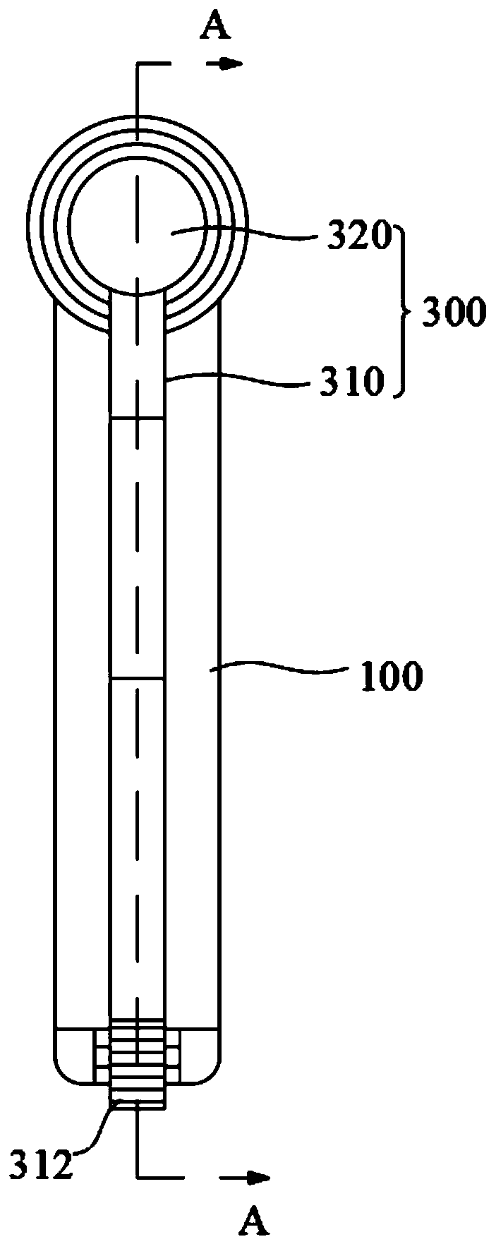
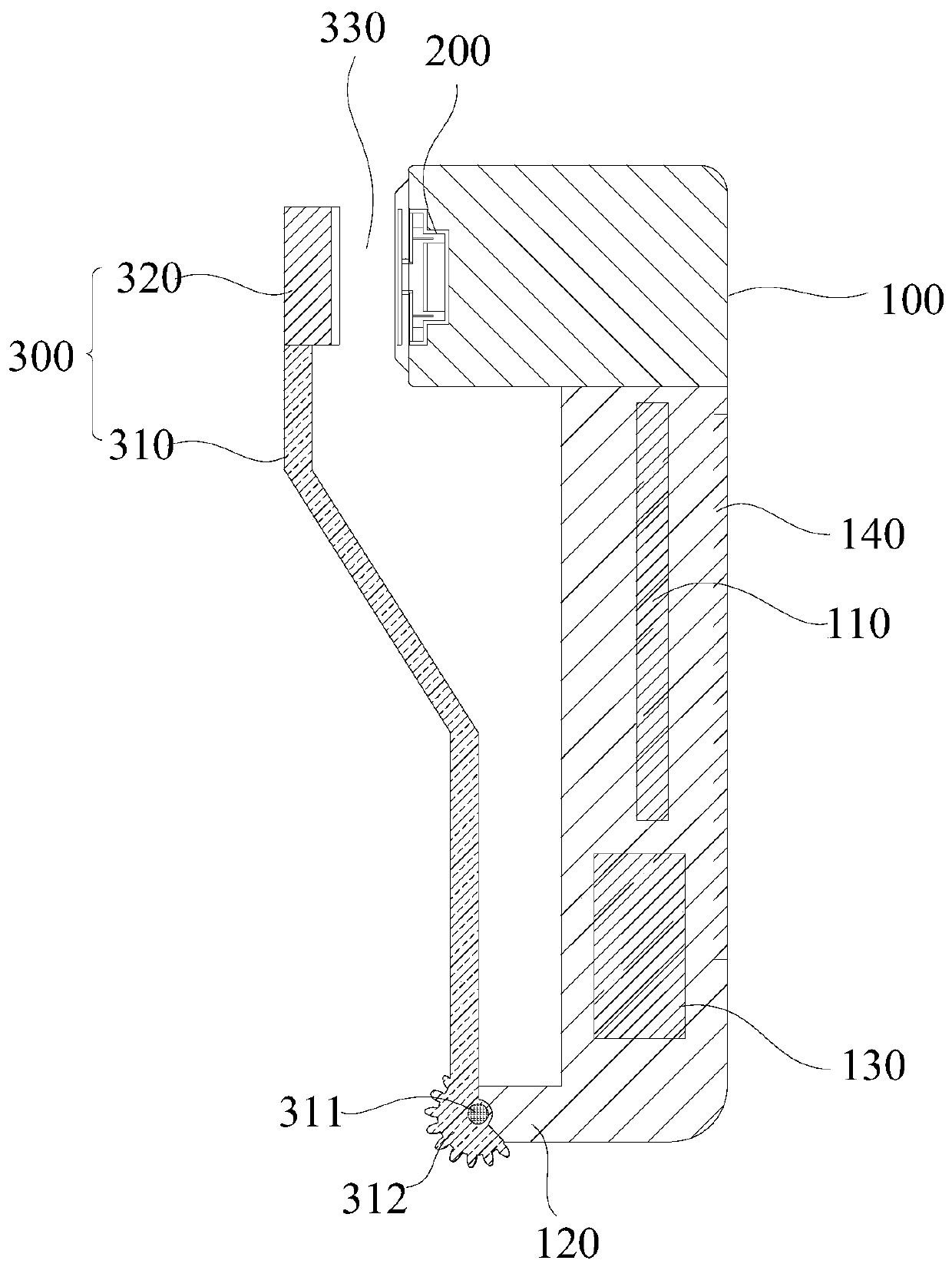
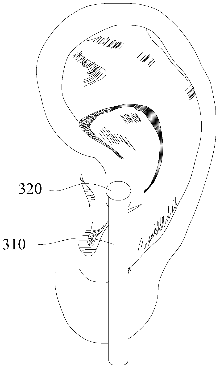
[0061] see Figure 1 ~ Figure 3, the clip-on ear-worn device provided in this embodiment includes an earphone main body 100 , a speaker module 200 and a clip part 300 . The earphone main body 100 is provided with a first PCB board 110 . The speaker module 200 is disposed in the head of the earphone body 100 , and the first PCB board 110 is electrically connected thereto. One end of the clamping portion 300 is movably fixed to the connecting end of the earphone body 100 . When the clip-on ear-mounted device is worn, the clip part 300 and the earphone main body 100 are respectively clamped on the outer side and the inner side of the ear, and the head of the earphone main body 100 is closely attached to the inner side of the ear. The clip-type ear-wearing device is fixed on the ear by clamping, and has the characteristics of being stable and not easy to fall off. The clip-on ear-mounted device does not close the ear canal when worn, and the user can still hear external sounds,...
Embodiment 2
[0075] refer to Figure 8 The difference between this embodiment and Embodiment 1 lies in that the connecting arms 2122b of the elastic piece 212b provided in this embodiment are radially fixed on the outer peripheral edge of the inner ring body 2121b. The shrapnel has the characteristics of easy processing and forming. In this embodiment, the inner ring body 2121b is circular, and those skilled in the art can directly replace the shape of the inner ring body 2121b with a triangle, a square, a racetrack shape, or an ellipse, and the replacement of the above technical features does not require Paying creative work belongs to equivalent replacement and should be included in the scope of protection of the present invention.
[0076] The rest of this embodiment is the same as that of Embodiment 1, and the features not explained in this embodiment are all explained in Embodiment 1, and will not be repeated here.
Embodiment 3
[0078] refer to Figure 9 The difference between this embodiment and Embodiment 1 lies in that the connecting arm 2122c of the elastic piece 212c provided in this embodiment is fixed on the outer peripheral edge of the inner ring body 2121c in a cantilever shape. In this embodiment, the inner ring body 2121a is triangular. Those skilled in the art can directly replace the shape of the inner ring body 2121c with a circle, a square, a racetrack shape, or an ellipse. The replacement of the above-mentioned technical features does not require Paying creative work belongs to equivalent replacement and should be included in the scope of protection of the present invention.
[0079] The rest of this embodiment is the same as that of Embodiment 1, and the features not explained in this embodiment are all explained in Embodiment 1, and will not be repeated here.
PUM
 Abstract
Description
Claims
Application Information
 - R&D
- Intellectual Property
- Life Sciences
- Materials
- Tech Scout
- Unparalleled Data Quality
- Higher Quality Content
- 60% Fewer Hallucinations
Browse by: Latest US Patents, China's latest patents, Technical Efficacy Thesaurus, Application Domain, Technology Topic, Popular Technical Reports.
© 2025 PatSnap. All rights reserved.Legal|Privacy policy|Modern Slavery Act Transparency Statement|Sitemap|About US| Contact US: help@patsnap.com


