Check patentability & draft patents in minutes with Patsnap Eureka AI!

Skeleton parts for automobiles

A component and skeleton technology, applied in the field of automobile skeleton parts, can solve problems such as difficult repair, light weight, low rigidity of foamed resin, etc.

Active Publication Date: 2022-05-13
JFE STEEL CORP
View PDF10 Cites 0 Cited by
  • Summary
  • Abstract
  • Description
  • Claims
  • Application Information

AI Technical Summary

Problems solved by technology

[0008] In addition, in the case of reinforcement of an automobile skeleton member composed of an outer panel and an inner panel, in general, bulkhead members such as metal bulkheads are often incorporated for the purpose of connecting the outer panel and the inner panel. , but they are not lightweight because they are larger components and therefore have a certain weight
In addition, there is also a method of injecting foaming resin or the like into the space formed by the outer panel and the inner panel as a whole, but since the rigidity of the foaming resin itself is low, a large increase in rigidity cannot be expected just by filling it. However, since it is necessary to inject the foamed resin into the entire frame member, it is difficult to confirm the filling state, so there is a problem in repairability

Method used


Image

  • Skeleton parts for automobiles
  • Skeleton parts for automobiles
  • Skeleton parts for automobiles

Examples


Embodiment 1

[0101] Since an experiment was conducted to verify the effect of improving the rigidity and reducing the weight of the automobile frame member according to the present invention, it will be described below.

[0102] In Example 1, as a skeleton part for an automobile, the Figure 7 as well as Figure 8 The optimal shape of the reinforced component model shown in 9 to set figure 1 as well as figure 2 The A-pillar lower side 1 of the reinforcement member 7 shown is an example of the invention, and the rigidity and weight reduction of the A-pillar lower side 1 were evaluated.

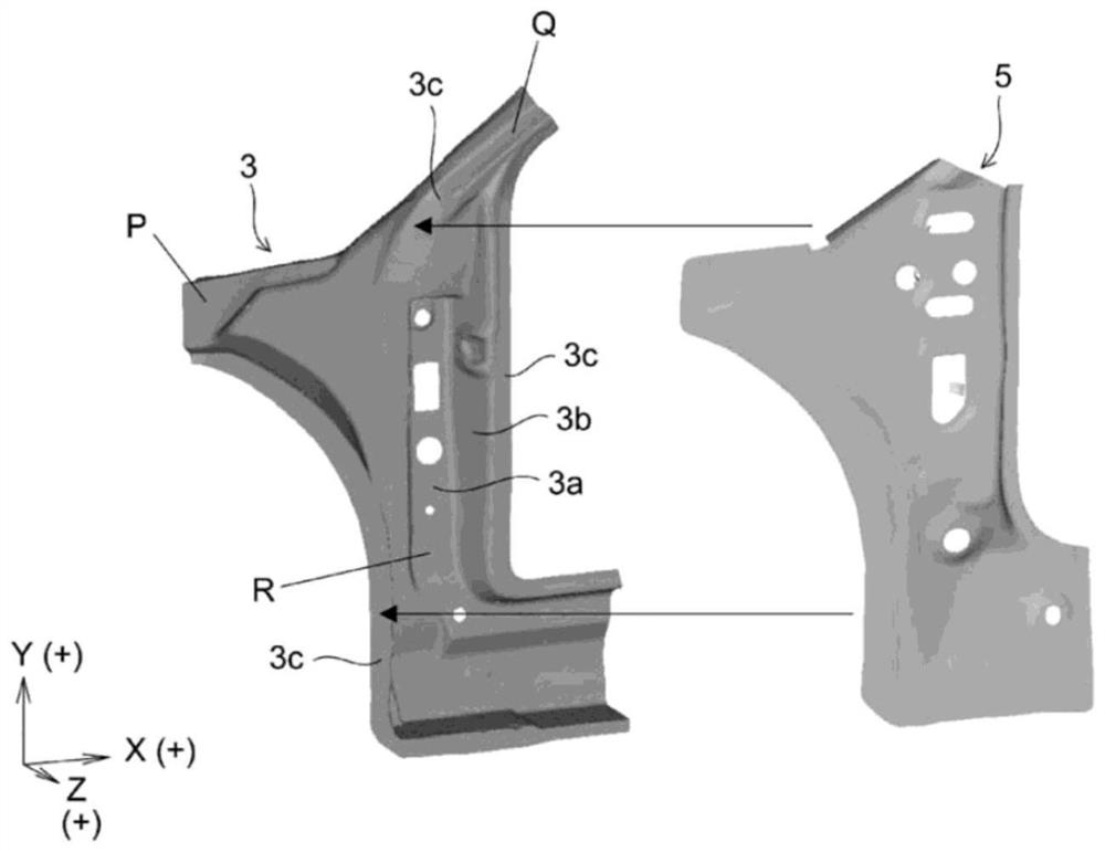
[0103] The A-pillar underside 1 according to Invention Example 1 is formed by joining the outer panel 3 and the inner panel 5, and the outer panel 3 and the inner panel 5 are alloys with a tensile strength of 440 MPa and a thickness of 1.0 mm. Manufactured by stamping hot-dipgalvannealed steel sheet.

[0104] Reinforcement part 7 ( figure 2 ) is based on the shape optimization analysis method describ...

Embodiment 2

[0131] Similar to the above-mentioned Example 1, an experiment was conducted to verify the effect of improving the rigidity and reducing the weight of the automobile frame member according to the present invention, and therefore it will be described below.

[0132] In this second embodiment, based on the analysis results of the shape optimization analysis, it is set Figure 15 as well as Figure 16 The shape and arrangement of the reinforcing member 33 shown were used to evaluate the rigidity and weight reduction of the A-pillar lower side 31 where the reinforcing member 33 was set.

[0133] First, setting of the shape and arrangement of the reinforcing member 33 by the shape optimization analysis method will be described.

[0134] exist Figure 18 An optimization analysis model 51 in the shape optimization analysis is shown in . The optimization analysis model 51 sets a design space in the space formed by the outer panel 3 and the inner panel 5 , and sets a reinforcement m...


PUM


Abstract

The lower side (1) of the A-pillar, which is the frame member for automobiles according to the present invention, has a substantially T-shape in plan view, and intersects with each position corresponding to the transverse and longitudinal sides of the substantially T-shape. The cross-section is the outer plate (3) of the hat-shaped cross-sectional shape that is made of top plate portion (3a), vertical wall portion (3b), flange portion (3c); and the flange portion (3c) with the outer plate (3) The inner plate (5) which is joined to form a closed section between the outer plate (3) and the inner plate (5) and the outer plate (3) are made of metal. In the space between the plates (5), a plurality of resin-made reinforcement members (7) are respectively bonded to the inner surface (3d) of the outer plate (3) at one end and the inner surface (5a) of the inner plate (5) at the other end, The shape and arrangement of the reinforcing member (7) are set based on the analysis results of the shape optimization analysis method, and the shape of the reinforcing member (7) has a columnar shape or a columnar shape with raised ends.

Description

technical field [0001] The present invention relates to automobile frame parts (automotive frame parts) made of metal, and more particularly to an automobile frame part in which a resin-made reinforcing member (stiffening member) is provided in a space formed by an outer panel (outer panel) and an inner panel (inner panel). ) A-pillar lower side (pillar-lower) parts (parts) of the car frame parts. Background technique [0002] There are many techniques for reducing the weight of metal skeleton parts of automobiles. For example, thinning of ultra high-tensile steel sheets, material replacement from steel sheets to aluminum sheets, and the like are applied. Although the number of stamped parts (press formed parts) changing from steel sheets to aluminum is increasing year by year, due to the unavoidable rise in material (base metal sheet) costs, aluminum die casting methods are being used recently. A method of manufacturing a shaped part including a plurality of surrounding p...

Claims


Application Information

Patent Timeline
Patent Type & Authority Patents(China)
IPC IPC(8): B62D25/04B62D65/00
CPCB62D25/04B62D65/00B62D29/005B60Y2304/03B60Y2306/01B62D25/08B62D27/023
Inventor 樋贝和彦齐藤孝信玉井良清
Owner JFE STEEL CORP
Features
  • R&D
  • Intellectual Property
  • Life Sciences
  • Materials
  • Tech Scout
  • Unparalleled Data Quality
  • Higher Quality Content
  • 60% Fewer Hallucinations
Learn More