
Urban overpass road network and operation mode thereof

A road network and urban technology, applied in the direction of roads, roads, bridges, etc., can solve problems with little effect, can not completely solve urban road traffic congestion, can not solve ground traffic congestion and other problems

Inactive Publication Date: 2020-05-12
徐子杰
View PDF0 Cites 0 Cited by
  • Summary
  • Abstract
  • Description
  • Claims
  • Application Information

AI Technical Summary

Problems solved by technology

[0002] Traffic congestion in modern cities is a world-class problem. So far there is no better solution. The existing solutions can be classified into three categories: one is to increase the usable roads, including expanding old roads, building new roads, and building parking lots, etc. , but since there is no extra land for use in the built-up area, this effort has had little effect. Although rail transit such as subways plays a significant role in transport capacity, it still cannot solve the problem of ground traffic congestion; second, restrict car purchase and use; third It is to make motor vehicles faster to reduce congestion, such as building overpasses and various overpasses, but their defects are that they cannot completely separate pedestrians and motor vehicles, so they cannot completely solve urban road traffic congestion; in order to overcome these defects, the applicant is This has been a long-term in-depth research and exploration

Method used


Image

  • Urban overpass road network and operation mode thereof
  • Urban overpass road network and operation mode thereof
  • Urban overpass road network and operation mode thereof

Examples


Embodiment Construction

[0067] The principles and features of the present invention are described below in conjunction with the accompanying drawings, and the examples given are only used to explain the present invention, and are not intended to limit the scope of the present invention.

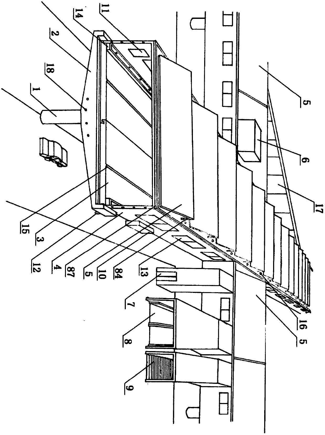
[0068]An urban overpass road network, including roadbed equipment, corridor equipment, and bridge ladder equipment; the roadbed equipment is built on the center line of the urban primary and secondary roads, and can be extended arbitrarily; the corridor equipment is built on the roadbed equipment to ensure pedestrians Pass through the city rain or shine; bridge ladder equipment is built at level crossings and places along the way that need to go up and down bridges.

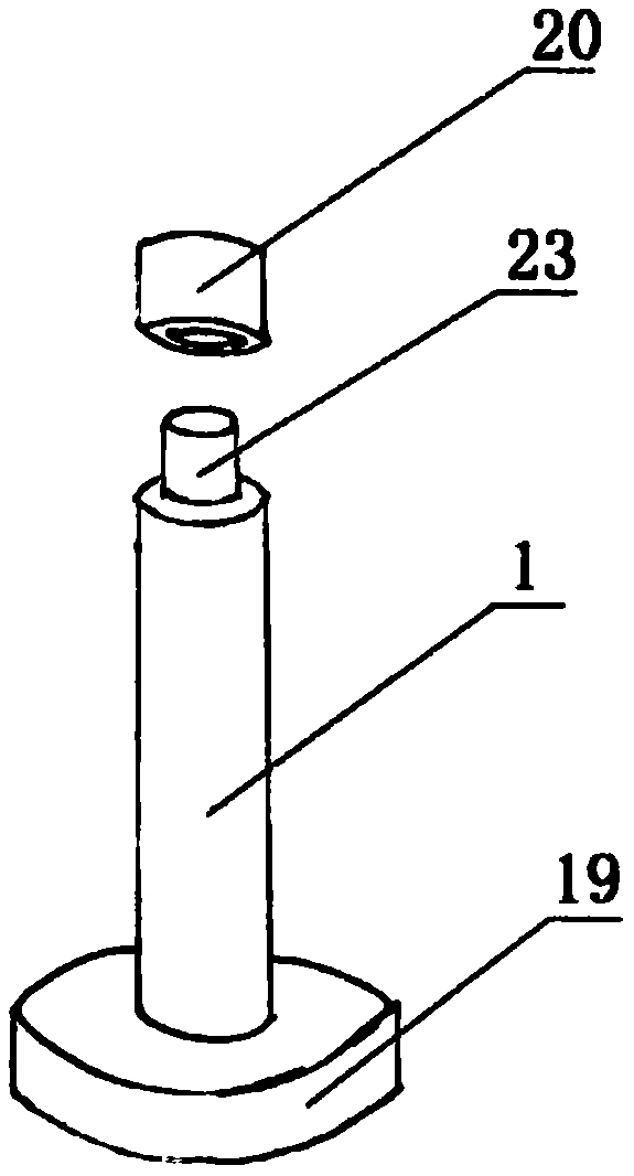
[0069] The roadbed equipment includes: support column 1, beam 2, road slab 3; (see Figure 1-Figure 5 ) The support column 1 is made by pouring reinforced concrete, and the underground end of the support column 1 has a load-bearing plate 19 to withstan...


PUM


Abstract

The invention relates to an urban overpass road network and an operation mode thereof, and belongs to the field of urban traffic planning. The urban overpass road network comprises roadbed equipment,corridor compartment equipment and bridge ladder equipment, the roadbed equipment supports the whole overpass road network, the whole overpass road network is all-around the overhead of the first-level and second-level main lines of a city, the corridor compartment equipment is built on the roadbed equipment, it is guaranteed that pedestrians are not obstructed by wind and rain, the bridge ladderequipment is built at each level crossing and each place where the pedestrians need to get on and off the overpass road network, and the pedestrians can get on and off the overpass road network conveniently; in addition, auxiliary devices such as a photovoltaic power generation system, an automatic fire extinguishing system, an automatic rainwater accumulation system, an automatic management greening system and a rest and leisure area are further arranged, so that the system has the functions of network all-around overpass road and pedestrian and automobile separation, and road congestion canbe solved. The corridor compartment greatly improves the traveling condition of the pedestrians; citizens can be well cared by the rest and leisure area; the construction cost and the operation cost are low; the overpass road network has the advantages of reasonable structure, safety, reliability, convenience in maintenance, resource conservation and the like.

Description

[0001] Technical field: The present invention relates to an urban overpass road network, which belongs to the field of urban traffic planning. Background technique: [0002] Traffic congestion in modern cities is a world-class problem. So far there is no better solution. Existing solutions can be classified into three categories: one is to increase usable roads, including expanding old roads, building new roads, and building parking lots, etc. , but since there is no extra land for use in the built-up area, this effort has had little effect. Although rail transit such as subways plays a significant role in transport capacity, it still cannot solve the problem of ground traffic congestion; second, restrict car purchase and use; third It is to speed up motor vehicles to reduce congestion, such as building overpasses and various overpasses, but their defect is that they cannot completely separate pedestrians and motor vehicles, so they cannot completely solve urban road traffic co...

Claims


Application Information

Patent Timeline
IPC IPC(8): E01C1/00E01D1/00E01C3/00
CPCE01C1/00E01C3/00E01D1/00
Inventor 徐子杰徐春义
Owner 徐子杰
Learn More