Automobile retrograde motion preventing device with self-cleaning function

A self-cleaning, functional technology, applied in the field of traffic safety, can solve problems such as large safety hazards, and achieve the effect of avoiding dust

Active Publication Date: 2020-05-12
台州市黄岩一鑫汽车零部件有限公司
View PDF8 Cites 10 Cited by
  • Summary
  • Abstract
  • Description
  • Claims
  • Application Information

AI Technical Summary

Problems solved by technology

[0005] The purpose of the present invention is to provide a relatively safe anti-vehicle retrograde device with self-clea

Method used


Image

  • Automobile retrograde motion preventing device with self-cleaning function
  • Automobile retrograde motion preventing device with self-cleaning function
  • Automobile retrograde motion preventing device with self-cleaning function

Examples


Example Embodiment

[0022] Example 1

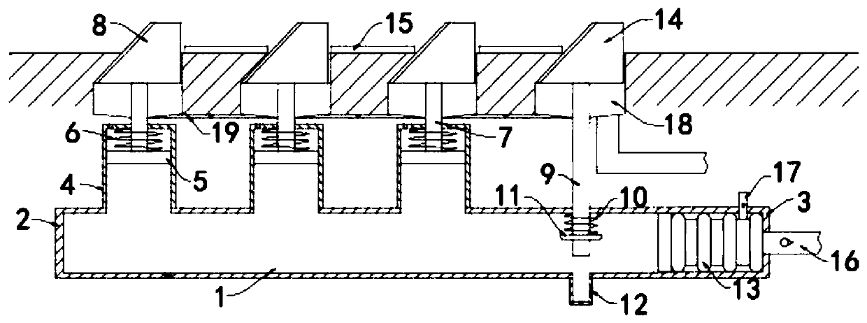
[0023] like Figure 1-2 As shown, a self-cleaning anti-vehicle retrograde device includes a main pipe 1 arranged below the ground and arranged horizontally. The side wall of the main pipe 1 is provided with a single row of air intake holes. The main pipe 1 has good wear resistance and sealing It can be an ordinary plastic pipe. The main pipe 1 includes a forward end 2 and a reverse end 3 with both ends sealed. The car travels from the forward end 2 to the reverse end 3. The end 2 runs in the reverse direction, and the upper side wall of the main pipe 1 is fixedly connected with a plurality of sub-pipes 4 that are all vertically arranged, and the upper ends of the plurality of sub-pipes 4 are all sealed.

[0024] Each branch pipe 4 is sealed and slidably connected with a horizontally arranged sliding plate 5, and a back-moving spring 6 is fixedly connected between the sliding plate 5 and the inner top surface of the branch pipe 4. The back-moving spring 6 is...

Example Embodiment

[0033] Example 2

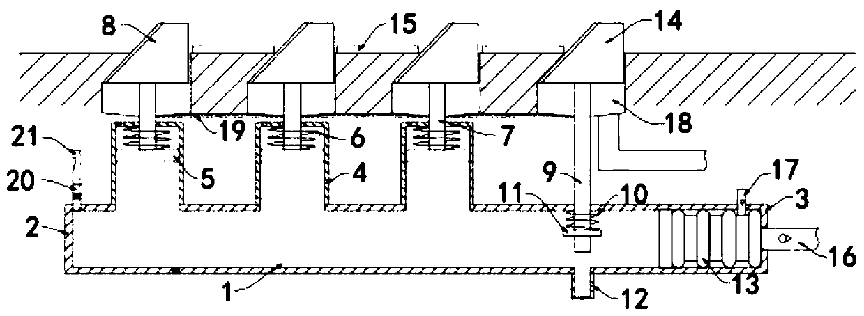
[0034] like image 3 As shown, the difference between this embodiment and Embodiment 1 is that an air outlet pipe 20 is fixedly communicated with the side wall of the antegrade end 2 of the main pipe 1, and the other end of the air outlet pipe 20 is fixedly connected with a warning whistle 21, and the air outlet pipe 20 There is a flow-limiting one-way valve inside, and when the air pressure in the main pipe 1 reaches the limit value of the flow-limiting one-way valve, the gas in the pipe will be discharged through the outlet pipe 20 .

[0035] In this embodiment, when the car is running in the reverse direction, the main anti-reverse belt 14 will be pressed into the sealing tube 12 first. Also can blow warning whistle 21 by air outlet pipe 20, carry out effective warning to driver.


PUM


Abstract

The invention, which belongs to the field of traffic safety, relates to an automobile retrograde motion preventing device with a self-cleaning function. The device comprises a main pipe which is arranged underground and is horizontally arranged. The main pipe comprises a forward end and a backward end, wherein the two ends of the forward end and the backward end are sealed; the upper side wall ofthe main pipe is fixedly communicated with a plurality of branch pipes which are vertically arranged; the upper ends of the branch pipes are sealed, a horizontally-arranged sliding plate is connectedinto each branch pipe in a sealed and sliding mode, reset springs are fixedly connected between the sliding plates and the inner top faces of the branch pipes, vertically-arranged connecting rods arefixedly connected to the upper side walls of the sliding plates, and the upper ends of the connecting rods extend to the exteriors of the branch pipes and are fixedly connected with anti-retrograde belts. When an automobile runs in the forward direction and rolls on the anti-retrograde belts, the air pressure in the main pipe can extrude elastic air bags, water in the elastic air bags is sprayed to the gaps between the anti-retrograde main belt and the multiple anti-retrograde belts through water spraying pipes, so that dust difficult to clean in the gaps is removed, and the situation that theautomobile passes through the belts to cause large flying dust is avoided.

Description

technical field [0001] The invention belongs to the field of traffic safety, in particular to an anti-vehicle retrograde device with self-cleaning function. Background technique [0002] In the process of road traffic management, traffic safety is of great significance. Every minute in our country, one person is injured and disabled due to a traffic accident, and among them, traffic accidents caused by vehicles traveling in the wrong direction account for a relatively large proportion. [0003] In road safety management, measures such as placing warning signs on the side of the road or setting speed bumps on the road in specific areas are usually used to reduce the occurrence of vehicles going against the road, but warning signs are often ignored by drivers, while speed bumps are It will affect cars traveling in the forward direction. Moreover, some traditional anti-reverse vehicle devices play a warning role by puncturing the tires of retrograde vehicles. , greater securit...

Claims


Application Information

Patent Timeline
IPC IPC(8): E01F13/10E01F9/619
CPCE01F13/10E01F9/619
Inventor 许钰杰薛博文
Owner 台州市黄岩一鑫汽车零部件有限公司
Why Eureka
Try Eureka